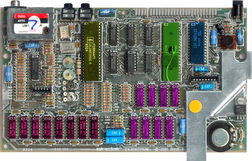
The ZX Spectrum motherboard is fairly straightforward by modern standards:

Integrated Circuits
Most of the chips are soldered to the board, with the exception of the ROM and the ULA
- IC1 – ULA
- IC2 – Zilog Z80A Processor
- IC3, IC4, IC23 to IC26 – Decoder / Multiplexor chips
- IC14 – LM1889N TV Video Modulator
- IC5 – HN613128P 16K ROM chip containing BASIC interpreter (&0000 – &3FFF)
- IC6 to IC13 – 4116 RAM chips for the lower 16K of memory (&4000 – &7FFF)
- IC15 to IC22 – 4532 RAM chips for the upper 32K of memory (&8000 – &FFFF)
Discrete Component Values
I’ve highlighted the most common parts that fail and may need replacing during ownership
- C25, C28, C34, C47, C50, C65 – 22µF 25V Axial
- C27, C46 – 1µF 63V Axial
- C44, C45 – 100µF 25V Axial
Note:
- C46 polarity printed on board indicates wrong polarity – install in reverse.
- C65 (incorrectly labelled as C14 on the diagram) was a ceramic capacitor on early revisions, so the polarity is not printed on the board. It should be mounted with -ve to the left.
- I normally use Vishay capacitors. Links to the components on the RS website.
Please note
The board pictured (an Issue 2, 48K) is the model that I currently own. The transistor (TR6) soldered over the Z80 processor is a patch to fix a bug in the Issue 2 ULA. TR6 is a ZTX313 and is connected to pins 11 and 30 of IC2 (the Z80) and pin 33 of IC1 (the ULA).
There are other variants with slightly different board layouts but the general principle of operation is the same.
In the schematic (link below), the RAS and CAS lines are drawn incorrectly for ICs 15 to 22. CAS connects to Pin 6 on IC23 and RAS to Pin 4, not the reverse as indicated.
