
A UART, or Universal Asynchronous Receiver/Transmitter is a computer chip that is designed to convert parallel data into a serial bit stream and transmit that data over a single wire. They contain a shift register that converts bytes to a bitstream, and vice versa, along with control logic to ensure that the CPU knows when it is safe to write or read data in the UART.
Typically 2 data lines are needed; a transmit (TX) and receive (RX), so that data can be sent and received at the same time, though extra wires can be used as signals for flow control, for example CTS – Clear to Send and RTS – Request to Send.
When connecting two devices together via UARTs, it is important to cross the lines, for example:
Device 1  RX > ----- < Device 2 TX
Device 1  TX > ----- < Device 2 RX
Device 1 CTS > ----- < Device 2 RTS
Device 1 RTS > ----- < Device 2 CTS
This section covers the 8250 serial UART and compatibles including the 16450 and 16550A. It will also cover compatible UARTs embedded in microcontrollers, such as the eZ80 series, and in FPGA simulations, such as the Spectrum Next. It is not intended to cover in any great detail the electrical characteristics of UARTs, nor the principles of writing a serial protocol.
I’ve greyed out any features in registers that are not part of the original 8250 spec, mainly to do with the FIFOs.
Flow Control
The basics of CTS/RTS flow control are as follows:
- The sender asserts its RTS (Request to Send) line (in the MCR) to indicate it has something to send
- The receive acknowledges that by asserting its CTS (Clear to Send) line when it is ready to receive the data
- The sender waits for the CTS (MSR) then sends the data
- The sender clears the RTS
- The receiver clears the CTS
With the UART, the MSR can be polled in a loop or read on interrupt
Registers
The UART chip contains 12 registers mapped to 8 ports as follows:
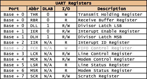
The UART designers employed a couple of strategies to fit the extra registers into 8 ports:
- Reuse the port twice for read-only and write-only ports, for example THR and RBR, IIR and FCR.
- Have a control bit in one of the registers (called DLAB) that switches in different registers when set, for example THR, DLL.
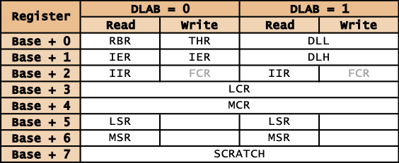
This is a different view that better highlights how that works:
Divisor Latches
Port: Base + 0 and Base + 1, with DLAB bit set (bit 7 of LCR)
The UART requires a 1.8432Mhz external clock signal to provide standard baud rates; this provides a maximum rate of 115200 baud, which is divided down internally to provide other common baud rates.
To set the baud rate in Z80, do something like this:
UART_PORT:         EQU     0x80            ; Example UART base port address

UART_REG_DLL:      EQU     UART_PORT+0     ; Divisor latch low
UART_REG_DLH:      EQU     UART_PORT+1     ; Divisor latch high
UART_REG_LCR:      EQU     UART_PORT+3     ; Line control

; Common baud rates
;
UART_BAUD:         EQU     115200          ; Maximum baud rate

UART_BAUD_1200:    DW      UART_BAUD/1200
UART_BAUD_2400:    DW      UART_BAUD/2400
UART_BAUD_4800:    DW      UART_BAUD/4800
UART_BAUD_9600:    DW      UART_BAUD/9600
UART_BAUD_14400:   DW      UART_BAUD/14400
UART_BAUD_19200:   DW      UART_BAUD/19200
UART_BAUD_38400:   DW      UART_BAUD/38400
UART_BAUD_57600:   DW      UART_BAUD/57600
UART_BAUD_115200:  DW      UART_BAUD/115200

; HL: Divisor
;
SET_BAUD:          LD      A,0x80: OUT (UART_REG_LCR),A    ; Turn DLAB on
                   LD      A,L:    OUT (UART_REG_DLL),A    ; Set the divisor low byte
                   LD      A,H:    OUT (UART_REG_DLH),A    ; Set the divisor high byte
                   LD      A,0x00: OUT (UART_REG_LCR),A    ; Turn DLAB off
                   RET

                   LD HL, UART_BAUD_9600
                   CALL SET_BAUD
RBR: Receive Buffer Register
Port: Base + 0 (Read Only)
In the 8250, this buffers can only hold a single byte for receive. Later UARTS like the 16550A have 16 byte buffers.
Sample code to receive a byte from the RBR:
UART_PORT:         EQU     0x80            ; Example UART base port address

UART_REG_RBR:      EQU     UART_PORT+0     ; Receive buffer (read)
UART_REG_LSR:      EQU     UART_PORT+5     ; Line status

; A: Data read
; Returns:
; F = C if character read
; F = NC if no character read
;
UART_RX:           IN      A,(UART_REG_LSR)                ; Get the line status register
                   AND     %00000001                       ; Check for characters in buffer
                   RET     Z                               ; Just ret (with carry clear) if none
                   IN      A,(UART_REG_RBR)                ; Read the character from RBR
                   SCF                                     ; Set the carry flag
                   RET
THR: Transmit Holding Register
Port: Base + 0 (Write Only)
In the 8250, this buffer can only hold a single byte for transmit. Later UARTS like the 16550A have 16 byte buffers. In either case, it is best practice to check bit 5 of the LSR to determine whether the THR is full. If that is set to 1, then the THR can accept data to transmit.
Sample code to transmit a byte only if the THR buffer is empty:
UART_PORT:         EQU     0x80            ; Example UART base port address

UART_REG_THR:      EQU     UART_PORT+0     ; Transmitter holding (write)
UART_REG_LSR:      EQU     UART_PORT+5     ; Line status

UART_TX_WAIT:      EQU     1024            ; Count before UART_TX times out


; A: Data to write
; Returns:
; F = C if written
; F = NC if timed out
;
UART_TX:           PUSH    BC                              ; Stack BC
                   PUSH    AF                              ; Stack AF
                   LD      B,low  UART_TX_WAIT             ; Set CB to the transmit timeout
                   LD      C,high UART_TX_WAIT
1:                 IN      A,(UART_REG_LSR)                ; Get the line status register
                   AND     %00100000                       ; Check for space in THR
                   JR      NZ,2F                           ; If set, THR can accept data, goto transmit
                   DJNZ    1B: DEC C: JR NZ,1B             ; Otherwise loop
                   POP     AF                              ; We've timed out at this point so
                   POP     BC                              ; Restore the stack
                   OR      A                               ; Clear the carry flag and preserve A
                   RET
2:                 POP     AF                              ; Good to send at this point, so
                   OUT     (UART_REG_THR),A                ; Write the character to the UART
                   POP     BC                              ; Restore the stack
                   SCF                                     ; Set the carry flag
                   RET
IER: Interrupt Enable Register
Port: Base + 1 (Read/Write)
The Interrupt Enable Register pretty much does what is says on the tin.
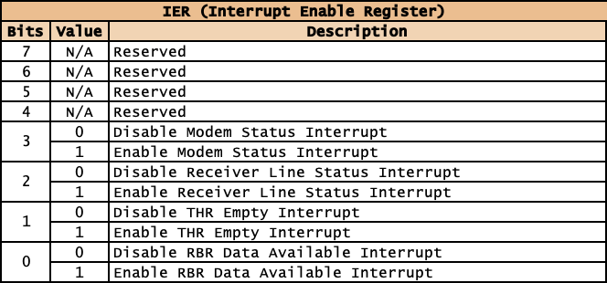
- The RBR Data Available Interrupt triggers when there is any data in the RBR Buffer.
- The THR Empty Interrupt triggers when there in no data in the THR Buffer.
- The Receiver Line Status Interrupt triggers when something in the LSR register changes.
- Similarly, the Modem Status Interrupt triggers when something in the MSR register.
IIR: Interrupt ID Register
Port: Base + 2 (Read Only)
There is only one interrupt pin on the UART, so to determine what triggered the interrupt, the IIR Register must be read.
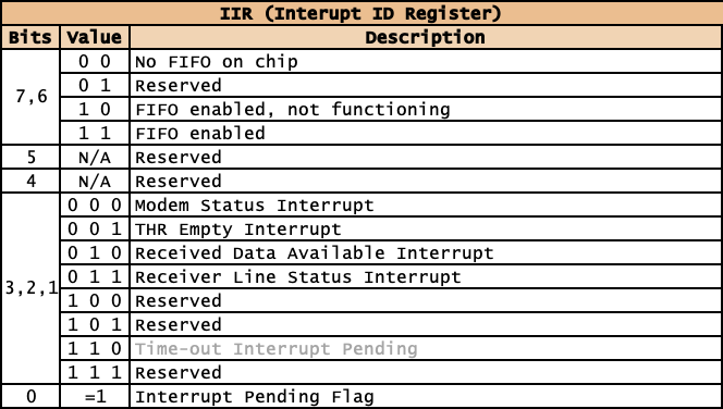
Bit 0 can be used to confirm that this UART was the one that triggered the interrupt, and then bits 1-3 can be used to determine the nature of the interrupt.
Bits 6 and 7 can be used to determine the hardware capabilities of the UART, i.e. whether it has a FIFO or not.
FCR: FIFO Control Register
Port: Base + 2 (Write Only, not supported by all UARTS)
A FIFO is a type of queue (First In, First Out); this type of queue ensures that the order of bytes transmitted is the same as the order of bytes written to the queue.
When bit 0 is set to 0, the UART will switch into 8520 compatibility mode, with a single byte THR and RBR.
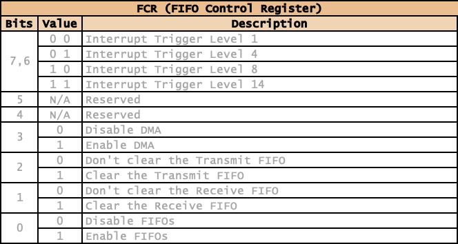
Bits 1 and 2 are used to clear either of the FIFOs.
Bit 3 enables and disables the DMA. This is linked to two pins on the UART, RXRDY and TXRDY. Unless the circuit the UART is connected to uses these pins, this bit can be safely ignored.
Bits 6 and 7 set the trigger threshold for the Received Data Available Interrupt.
LCR: Line Control Register
Port: Base + 3 (Read/Write)
The LCR register has two purposes:
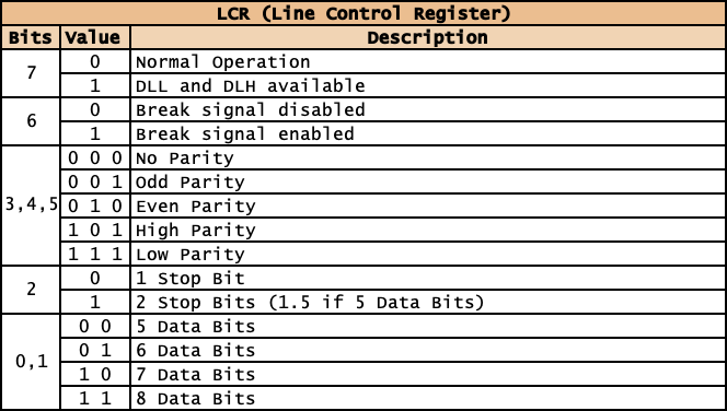
Bit 7 is used to switch in DLL and DLH, the divisor latches that set the effective baud rate. Set to 1 to access the latches, and 0 once the divisors have been set.
Bits 0 to 6 are used to set the serial data protocol, so for example 8 data bits, no parity, 1 stop bit = %00000011
MCR: Modem Control Register
Port: Base + 4 (Read/Write)
The MCR Register is used for flow control. For most modern use case scenarios you will either not use flow control, in which case this register can be ignored, or you will be setting/clearing the RTS and/or the DTR pins to signal to the device at the other end.
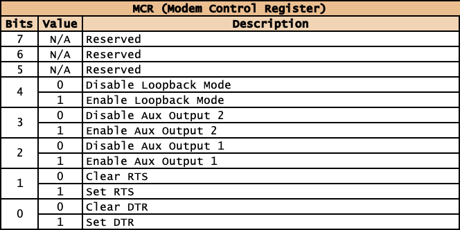
The AUX pins are two spare output pins on the UART. These are unlikely to be connected in anything other than a custom circuit.
And finally Loopback Mode switches the UART to loopback mode, so that comms can be tested between the CPU and the UART with no device connected.
LSR: Line Status Register
Port: Base + 5: Read Only
The LSR Register is used to determine the internal state of the UART.
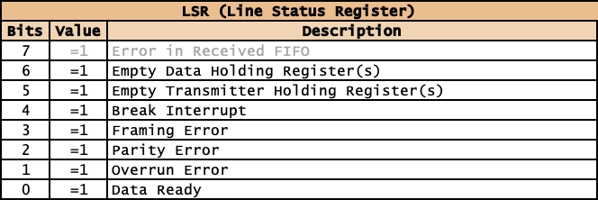
When bit 6 is set, all characters have been transmitted from the THR and bit 5 is set when the UART is capable of receiving more characters.
Bits 5 to 1 can be used to check for various comms errors, and bit 0 is set, there is data to be read from the RBR.
MSR: Modem Status Register
Port: Base + 6: Read Only
The MSR Register is used to determine the state of the modem.
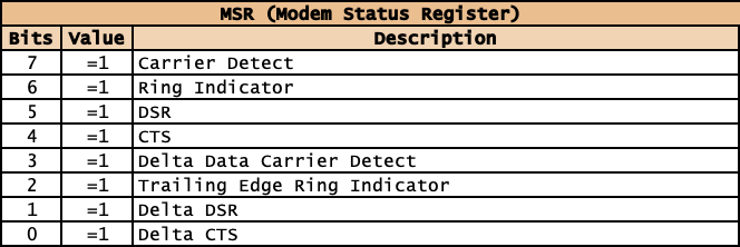
For systems where two UARTs are directly connected, the only bits that are likely to be used will be to do with DSR and CTS, which will be set by the connected device.
The delta bits will be set to 1 if there is a change in the associated signal.
SCR: Scratch Register
Port: Base + 7: Read/Write
A byte of data can be stored in, and read from the SCR register. It has no bearing on the operation of the UART.