
The Spectrum screen memory map is split into two sections:
- 6144 bytes worth of bitmap data, starting at memory address &4000
- 768 byte colour attribute data, immediately after the bitmap data at address &5800
Bitmap data
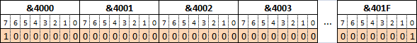
The bitmap data starts at address &4000 and consists of 192 lines of 32 bytes. Pixels are encoded as bits; 32 x 8 gives the horizontal resolution of 256 pixels. This example is a layout of the top line of the display with the pixels set at X position 0 and 255.
The display lines are not placed linearly; that is, each line is not 32 bytes beneath the one above it. To calculate the screen address of a byte, you encode the address as follows:
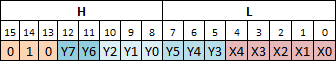
Where:
- The base address of screen memory (&4000) is provided by setting bits 15 to 13 to 010.
- Y0 to Y7 is the Y coordinate (in pixels)
- X0 to X4 is the X coordinate (in bytes)
Note the bit positions of Y0-Y2 and Y3-Y5 are transposed. The advantages of this is that you can quickly get to the next line within a character boundary by increasing the high byte of the address. The disadvantage is that the code to calculate the screen position or get the next line past a character boundary is quite convoluted:
; Get screen address
;  B = Y pixel position
;  C = X pixel position
; Returns address in HL
;
Get_Pixel_Address:	LD A,B		; Calculate Y2,Y1,Y0
			AND %00000111	; Mask out unwanted bits
			OR %01000000	; Set base address of screen
			LD H,A		; Store in H
			LD A,B		; Calculate Y7,Y6
			RRA		; Shift to position
			RRA
			RRA
			AND %00011000	; Mask out unwanted bits
			OR H		; OR with Y2,Y1,Y0
			LD H,A		; Store in H
			LD A,B		; Calculate Y5,Y4,Y3
			RLA		; Shift to position
			RLA
			AND %11100000	; Mask out unwanted bits
			LD L,A		; Store in L
			LD A,C		; Calculate X4,X3,X2,X1,X0
			RRA		; Shift into position
			RRA
			RRA
			AND %00011111	; Mask out unwanted bits
			OR L		; OR with Y5,Y4,Y3
			LD L,A		; Store in L
			RET
Colour attribute data
The colour attribute data overlays the monochrome bitmap data and is arranged in a linear fashion from left to right, top to bottom.
Each attribute byte colours an 8×8 character on the screen and is encoded as follows:
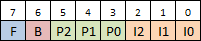
Where:
- F sets the attribute FLASH mode
- B sets the attribute BRIGHTNESS mode
- P2 to P0 is the PAPER colour
- I2 to I0 is the INK colour
So for each 8×8 character position you can only set two colours; this limitation is the sole cause of what is affectionately known as “attribute clash”.
Why is the Spectrum screen memory organised this way?
When the ULA is drawing the screen, it needs to make two fetches from DRAM, for the pixel data and the attribute data. In order to make this more efficient, the ULA uses DRAM page read mode. The advantage of this mode is that the bytes can be read quicker, but there is a limitation: the least significant 7 bits of the address being read must be the same.
So it follows that if you take any memory address in the bitmap area and its corresponding attribute, only the most significant 9 bits change.
For example: take screen address 16897 and its corresponding attribute address 22259:
16897 = 010000100 0000001
22259 = 010110000 0000001
If the memory were to be laid out differently, i.e. the bitmap was linear, it would not be guaranteed that those least significant bits would match.
This does work in the programmers favour if just working in character blocks. To move to the next pixel line within the character, you just need to INC H (assuming the address is in HL). It only starts getting complicated when moving to the next line, and the next third.