
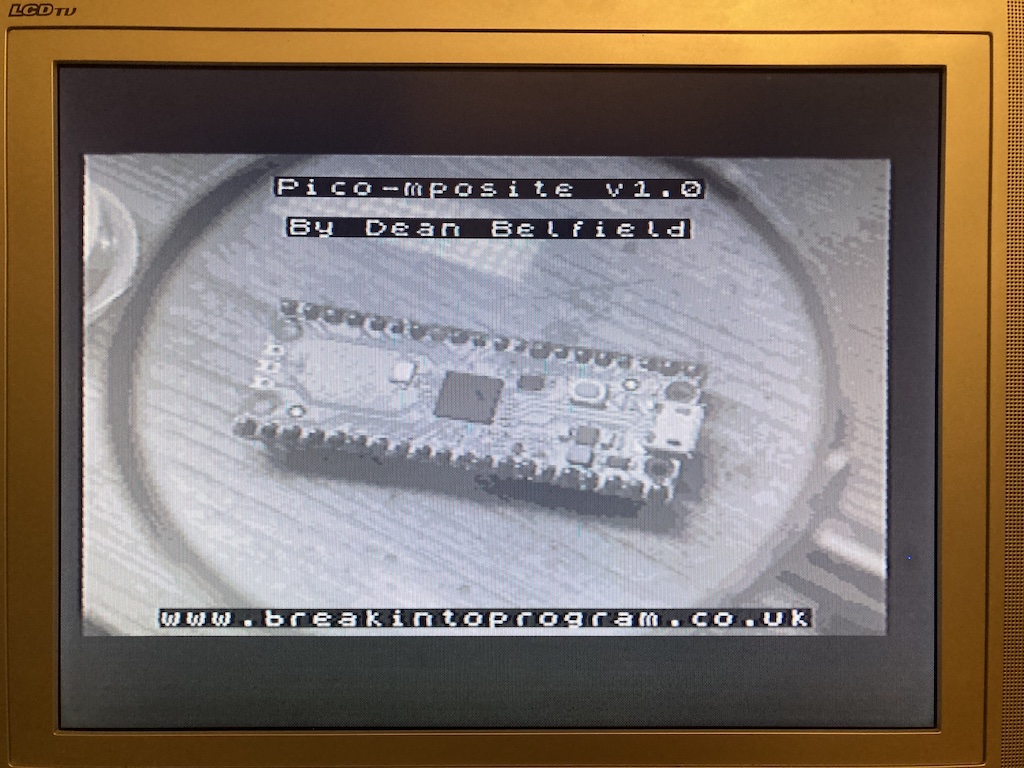
Pico-mposite Update
About this time last year I started a simple project for the Raspberry Pi Pico to output grey-scale composite video via a simple circuit using a 5-step resistor ladder. The Pico had not been out for very long, and I was attempting to use the PIO to output the video signal. Whilst I got it working, it did feel rather hacked together.
But I left it on my Github as a quick project: https://github.com/breakintoprogram/pico-mposite
During lockdown I wondered whether I could extend the circuit to add colour to the video output. There are a couple of ways to do this, either in software with additional bit-banging, or hardware. I decided to go down the hardware route, using an AD724 NTSC/PAL encoder chip. This requires the video signal from the Pico to be output in a slightly different way, with three levels for red, green and blue, and separate TTL levels for HSYNC and VSYNC.
The original Pico-mposite code wasn’t really suitable for the task, and after a couple of false starts trying to bodge it further, decided a rewrite was required.
The main change is the video generation is now split between two PIO state machines.
The Science Bit
The first state machine generates an empty scaffold PAL signal using a handful of small lookup tables. Each byte represents a 2μs pulse of low and high voltages. This is sufficient resolution to encode the vertical and horizontal blank signals, with a 32 byte table representing the 64μs horizontal line signal.
This code works pretty much the same way as the original; a DMA is set up to feed a state machine with a single horizontal line of data (32 bytes). After each line has been read from memory, an interrupt occurs to set the DMA up with the next lines sync data.
This data is written out to 5 of the Pico GPIO pins, feeding the resistor ladder to generate a voltage between 0 and 1V.
The second state machine generates the pixel data. It waits for an IRQ to be set from the first state machine, which occurs when a zero byte is detected in the horizontal sync table. This state machine then pulls 256 bytes from a second DMA channel, writing that data out to same GPIO pins as the first. In the meantime, the first state machine runs NOP instructions until it detects a non-zero byte in its DMA stream.
At the end of the pixel stream a second IRQ is triggered; this triggers an interrupt that sets up the DMA to read the next row of pixel data.
The State of Play
This code is a lot easier to tweak than the first. For example the horizontal video resolution can be changed easily. And the data structures are more intuitive; the initial version encoded the line blanking and sync at pixel resolution, so required each line to be padded out by 126 bytes to accommodate that encoded signal, with a zero at the end to encode end of line for the PIO. This version just requires a square bitmap array of the appropriate dimensions, either in ROM (static image) or RAM.
The new code is not fully optimised; it’s been written for clarity rather than cleverness, yet perhaps will serve as an example on how to use the PIO and DMA features of the Pico.
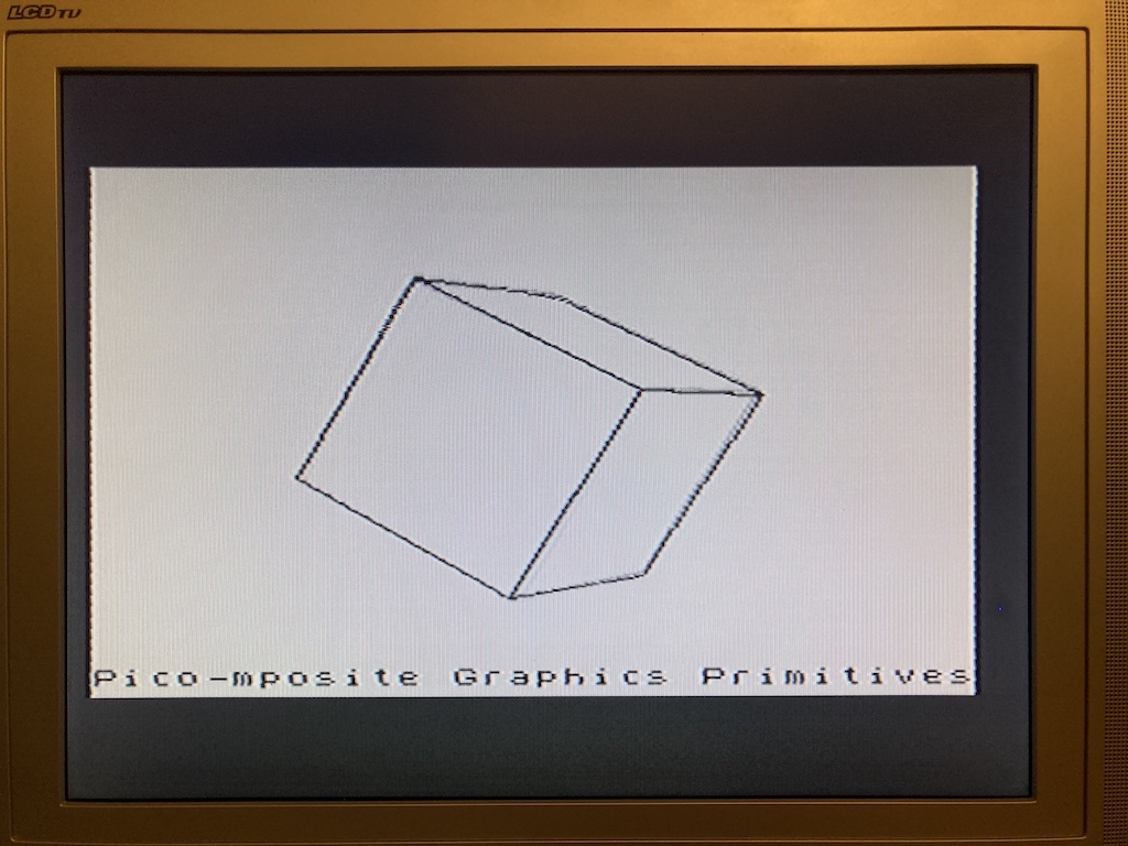
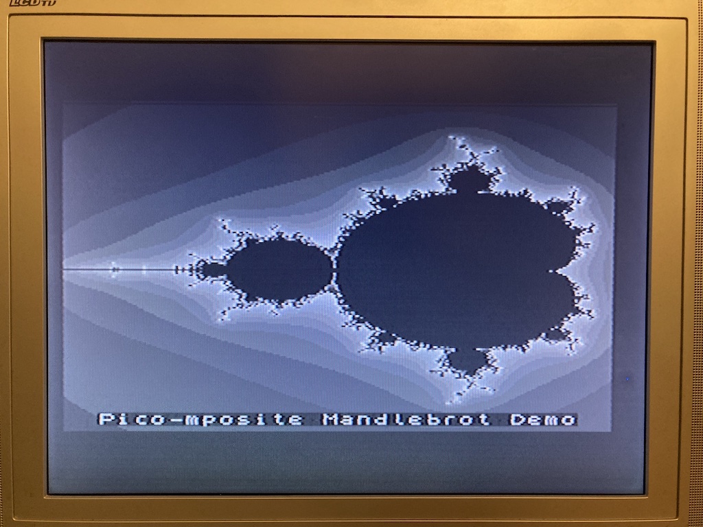
In addition, I’ve done some housekeeping on the code, refactoring it to make it more usable. I’ve also includes a handful of extras to get folk started on projects based upon this; some graphics primitives (Plot, Line, Circle, Print), and a rolling demo to demonstrate how to use them.
The code is available on the same GitHub (link at top of article).
What’s Next…
What of the colour version of Pico-mposite. I should be able to adapt this version quite easily to work with that; the PIO generating the SYNC signals can be fed directly into the AD724, and the pixel data split through three smaller resistor ladders to feed the AD724 RGB pins. And I’m hoping I can do this with some conditional compilation, to simplify code maintenance. Or at least that’s the theory.