
Composite Video on the Raspberry Pi Pico
I received my Pico a day or so after it was announced, and felt a little bit like a mule with a spinning wheel at first – was there a project I could start on this that would also serve as an introduction to key parts of the hardware, and could be completed in a few days.
I was interested in the PIO feature of the Pico – this is a cut down core in the RP2040 silicon that runs a very cut-down assembly language instruction set to shift GPIO data back and forth. And have been looking at composite video signals for a while on various projects. That got me thinking. The Pico doesn’t have dedicated video hardware. Could I repurpose the GPIO and use the PIO to output a composite video signal?
So I set myself some design targets:
- Use the PIO to render each horizontal scanline
- Use DMA to feed the PIO with pixel data
- Target resolution of 256 x 192 pixels with a border
- Try to keep CPU code to a minimum
- Simple supporting circuitry
- A cool name for the project
I settled on pico-mposite for the project name. You can find all the files for this, including schematics, on my Github project page here.
There is a caveat for this project; it works fine on my old Samsung TV. However, aficionados of vintage equipment will be well aware that modern TVs sometimes do not play ball with the slightly off-standard signals being output by retro computers and consoles, so your actual mileage with my code may vary.
Parts List
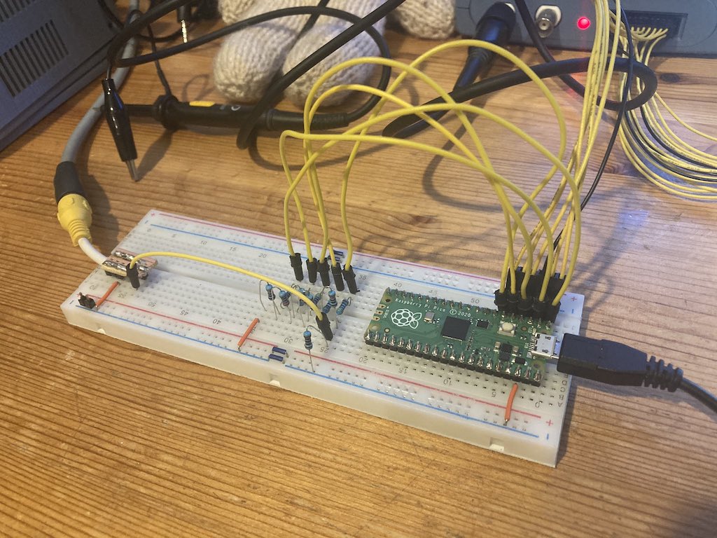
- A Raspberry Pi Pico with header pins soldered on
- An 830 point breadboard or similar
- 5 x 440Ω resistors
- 5 x 220Ω resistors
- 1 x 110Ω resistor
- Breadboard jumper cables
- Ideally an RCA socket, or some way to connect to the composite in on your TV
Note that the resistor values are approximate. I ended up using 470Ω, 220Ω and 100Ω resistors with no issues.
The Circuit Design
I looked at using PWM on a single pin, but couldn’t see a clear way to do that out of the box. And the Pico does not have any analogue outputs. My solution was to combine 5 consecutive GPIO pins using a resistor ladder circuit and roll my own analogue output between 0v and 1v, the range required for composite video.
It looks a little like this:
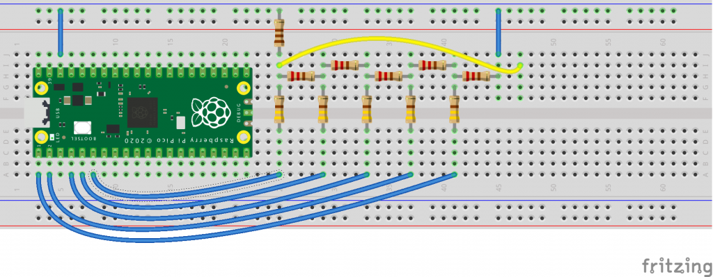
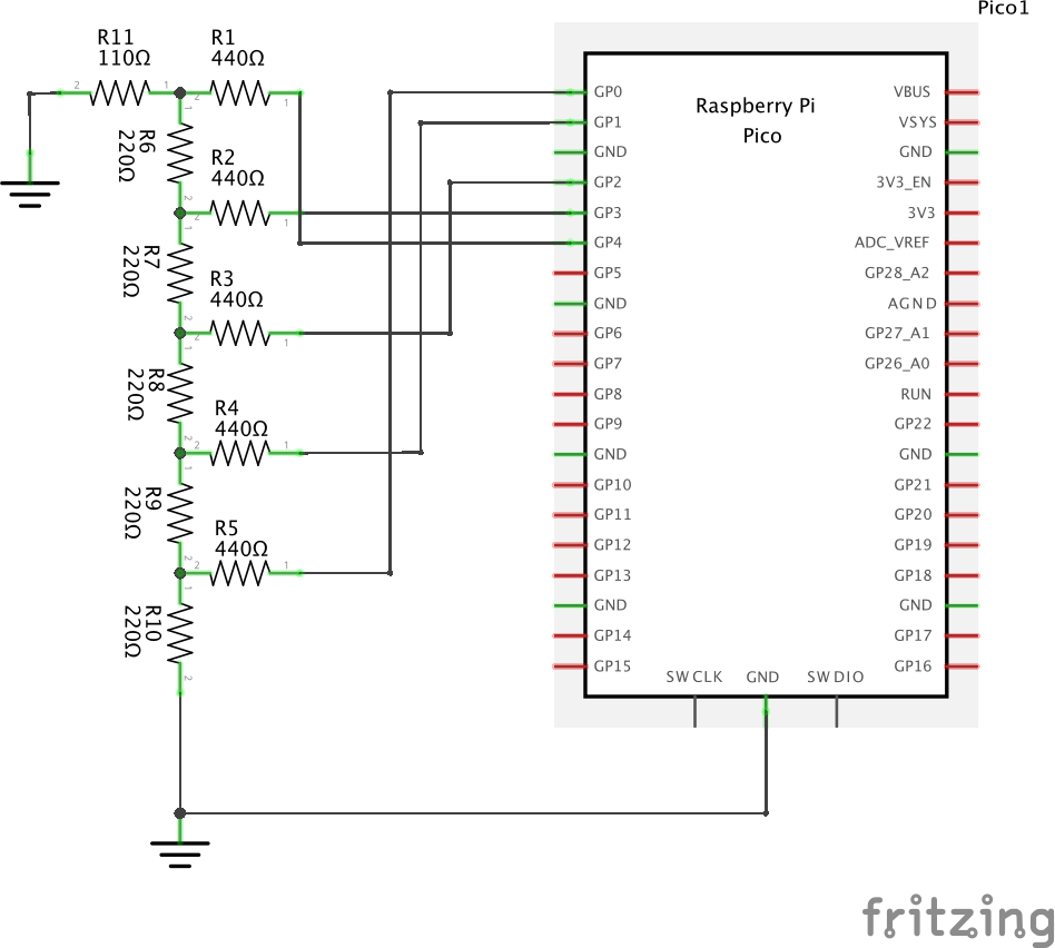
The output is taken from the junction of the leftmost resistors; I’ve pulled that over to the right hand side of the board for convenience and fed it into the inner core of a composite video socket. The outer sheaf of the socket is connected to one of the ground pins of the Pico.
Using this circuit if I set the GPIO pins to 00000, the output of the resistor ladder is 0v, and if I set it to 11111 then the output will be 1v, with a linear scale of voltages in-between.
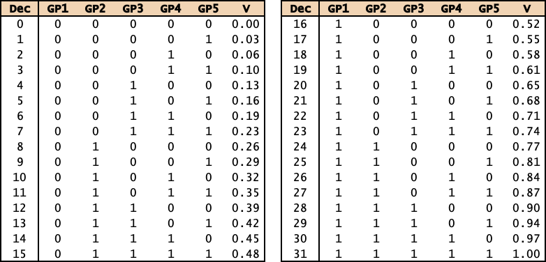
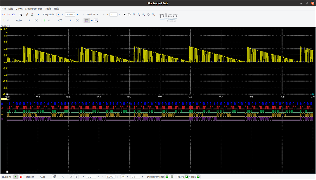
And you can see that demonstrated here on my scope, which is amusingly a Picoscope, but is not related. I’ve written test code on the Pico to count from 0 to 31 on the first 5 GPIO pins, and I’ve combined those GPIO values with the analogue output from the resistor ladder displayed above in yellow.
The Code
The next step was to write code on the Pico to generate a PAL scanline.
- Each horizontal scanline lasts 64μs (micro-seconds).
- Horizontal line sync (4μs @ 0v)
- Back porch (8μs @ 0.3v) *
- Pixel data (52μs @ 0.3v to 1v)
* I’m starting off with a greyscale picture to start off with; a colour signal would contain a colour burst sync in the back porch.
If you look these voltages up in the table, they correspond to:
- 0.0v = 0
- 0.3v = 9
For convenience, I’ll not use 0 for the horizontal line sync. I’m going to reserve that as a marker for end of sync, so will use 1 for that low pulse. It will be around 0.03v, but close enough I think.
The next step was to write the PIO code to output a 64μs pulse that contained the line sync pulses and some pixel data. I wasn’t going to bother with the vertical sync at this point as every line was going to contain the same data; a series of vertical stripes on screen. To achieve this I decided upon the following approach:
- Create an array in memory that will contain the voltage values I want to output via PIO.
- Hook this up to the DMA, so I can quickly feed the PIO with data.
- Combine the 5 pins of the GPIO so that I can write 1 value between 0 and 31 to set all the pins at once.
- Calculate a frequency for the PIO state machine that allows me to approximate the target resolution.
This approach requires minimal PIO code; it is designed to write out a burst of voltages from a buffer to the GPIO until it hits a 0 in the buffer. It doesn’t care what the voltages represent. I can then encode the line sync and pixel data in one buffer to be written out, and ensure that the buffer is long enough to occupy the PIO for the required 64μs.
The PIO code looks something like this:
.wrap_target            ; This loop needs to last 64us
    irq set 0           ; Set the IRQ to reset the buffer and do not wait
 loop:
    out X, 8            ; Get 8 bits from DMA via Output Shift Register (OSR) to X
    mov pins, X         ; Move X to pins as set up in cvideo_initialise_pio
    jmp X-- loop        ; Loop while X != 0
.wrap                   ; Loop back to wrap_target
The way that the PIO has been initialised is that the OSR is being fed from the DMA.
I mentioned earlier that I was going to reserve the GPIO value 0 for end of sync; it is a simple check to see whether the value pulled from memory is a 0. As you can see from the above code the inner loop will run while X (the data fetched from memory) doesn’t equal 0.
One final thing to mention about the PIO code. On line 2 I set the IRQ flag. The pico-mposite code running on the CPU cores will handle that interrupt and use it to set the DMA transfer up for the scanline.
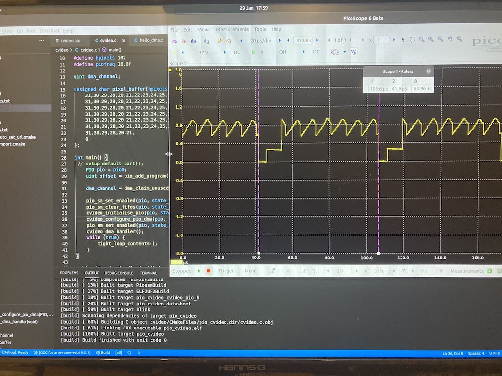
So how does that look on the scope, and on the monitor?
Next step is to add in the vertical sync signals. I’m going to keep this simple for the time being and output a non-interlaced field of 312 rows. Normally a PAL signal is interlaced, with the first field containing 312 rows and the second 311. Outputting two identical fields of 312 will put the timing out on the monitor ever so slightly, as it will get a second field with an extra row, but it should cope.
The following vertical sync pulses are required:
- Lines 1 and 2: Long + Long
- Line 3: Long + Short
- Lines 4, 5, 310, 311 and 312: Short + Short
Each vertical sync is formed of two half bursts of 32μs. A long sync consists of a 30μs pulse @ 1v followed by a 2μs pulse at 0v. A short sync is a 2μs pulse @ 1v followed by a 30μs pulse at 0v. As this is just more voltage data, I decided to set up 3 buffers to contain the 3 different 64μs vertical pulse combinations, and write them out using the same PIO code as the pixel data.
The aforementioned interrupt code handles the horizontal sync data. This interrupt runs once every 64μs at the start of every horizontal blank, so effectively a horizontal blank interrupt running on the main CPU cores.
// The hblank interrupt handler
// This is triggered by the instruction irq set 0 in the PIO code (cvideo.pio)
//
void cvideo_dma_handler(void) {

    // Switch condition on the vertical scanline number (vline)
    // Each statement does a dma_channel_set_read_addr to point the PIO to the next data to output
    //
    switch(vline) {

        // First deal with the vertical sync scanlines
        // Also on scanline 3, preload the first pixel buffer scanline
        //
        case 1 ... 2:
            dma_channel_set_read_addr(dma_channel, vsync_ll, true);
            break;
        case 3:
            dma_channel_set_read_addr(dma_channel, vsync_ls, true);
            memcpy(&pixel_buffer[bline & 1][pixel_start], &bitmap[bline], width);
            break;
        case 4 ... 5:
        case 310 ... 312:
            dma_channel_set_read_addr(dma_channel, vsync_ss, true);
            break;

        // Then the border scanlines
        //
        case 6 ... 68:
        case 260 ... 309:
            dma_channel_set_read_addr(dma_channel, border, true);
            break;

        // Now point the dma at the first buffer for the pixel data,
        // and preload the data for the next scanline
        //
        default:
            dma_channel_set_read_addr(dma_channel, pixel_buffer[bline++ & 1], true);    // Set the DMA to read from one of the pixel_buffers
            memcpy(&pixel_buffer[bline & 1][pixel_start], &bitmap[bline], width);       // And memcpy the next scanline into the other pixel buffer
            break;
    }

    // Increment and wrap the counters
    //
    if(vline++ >= 312) {	// If we've gone past the bottom scanline then
        vline = 1; 		// Reset the scanline counter
        bline = 0;		// And the pixel buffer row index counter
    }

    // Finally, clear the interrupt request ready for the next horizontal sync interrupt
    //
    dma_hw->ints0 = 1u << dma_channel;
}
The bulk of the code is the switch statement; this takes the vertical line counter stored in the global variable vline and decides which buffer to point the DMA at. This is either one of the three vsync buffers (vsync_ss, vsync_ll, vsync_ls) or the border buffer. This buffer contains a solid shade of gray so that I can have a border at the top and bottom of the main display.
Finally, the default is to draw pixel data. There is an array called pixel_buffer which holds two complete rows of video buffer data, including the horizontal sync pulses, a border, and 256 pixels of screen data.
The idea is that the DMA is pointed to one of these buffers to output the current scanline. Whilst the PIO is drawing that scanline, the CPU can then preload the next scanline into the other buffer. These alternate every scanline, and the first row of pixel data is set up during the vertical blank.
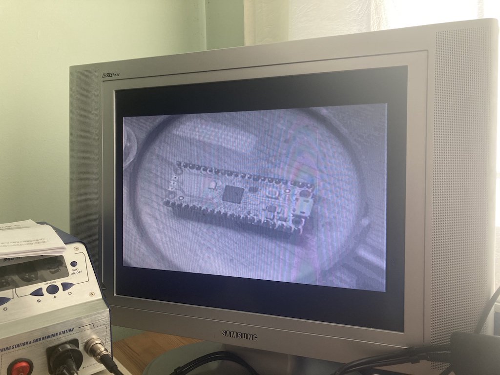
All I needed was a sample image. I took an image of a Pico, converted it to a 256×192 greyscale PNG in Gimp, and munged it using Python and the PIL library to output a C array of the data, with the greyscale values between 0x10 and 0x1F, to give 16 shades of grey.
And voila!
Update: 15/02/2021
I tweaked the code to use less RAM by updating the pixel data from the bitmap to the buffer for the DMA during the horizontal sync interrupt; this saves approximately 71K of RAM at the expense of a memcpy for each of the 192 rows of pixel data.
This article and the GitHub source have been updated accordingly.
Update: 31/01/2022
There’s a new version of Pico-mposite on the Github now that is improved in many ways. This article explains some of the changes, and why I decided to make them.