Pico-mposite Colour
My first project on the Pico was the Pico-mposite, a breadboard circuit and application that demonstrated how to generate a black and white composite video signal in software using the Pico’s PIO cores and DMA and a resistor ladder as a digital to analogue convertor.
The project went through a couple of iterations; from a hacked together demo to something that was a bit more usable and, more importantly, was ready, at least in principle for the third iteration – adding colour.
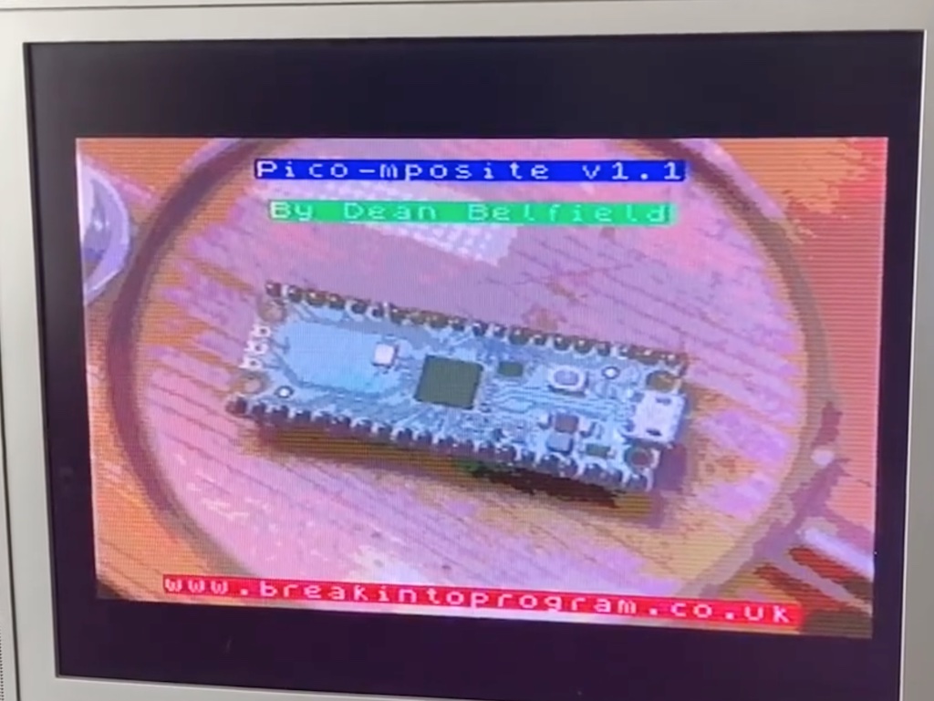
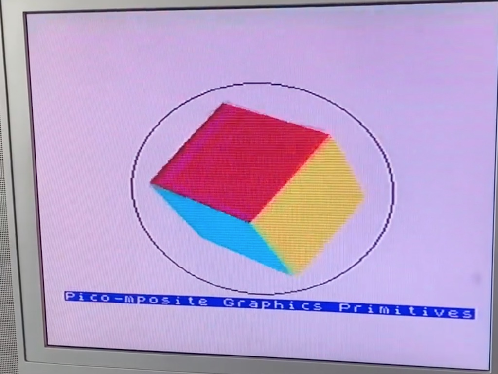
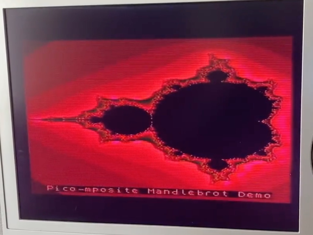
And here it is.
You can find all the the files for this project here on my GitHub project page.
How does colour work
Composite color video signals are generated by combining three primary color signals: red, green, and blue. The process involves encoding the intensity of each color and combining them to create a single signal that represents a full-color image.
The original image is represented in terms of its red, green, and blue components. Each component is a grayscale image representing the intensity of that particular color. These RGB signals are then converted into the YCbCr color space. Y represents the luma (brightness) component, while Cb and Cr represent the chroma (colour) components.
The Y, Cb, and Cr signals are then combined to create a composite video signal. In the case of standard definition composite video, this is typically done using amplitude modulation. The Y signal is modulated onto a carrier frequency, and the Cb and Cr signals are modulated and added to the Y signal to create a composite video signal.
Finally a colour burst signal, which provides a phase reference, is added to the monochrome horizontal sync signal.
The beauty of this system is that the extra colour information is ignored by monochrome equipment and, if detected by colour equipment, will identify the signal source as being colour rather than monochrome.
How does the Pico-mposite Colour board implement this
The Pico-mposite Colour is quite similar in practice to the monochrome version, with two main differences.
Instead of one resistor ladder for 32 levels of monochrome luminance (5 bits), there are three resistor ladders, one each for red, green, and blue. The red and green resistor ladders are 3 bit (8 levels of luminance) and the blue is 2 bit (4 levels). Each ladder is normalised so that the lowest level is 0V and the highest level is approximately 700mV, the upper limit of the AD724 chip. This number of bits was chosen to fit into a byte using 3-3-2 quantisation, a fairly common system where one byte represents one colour pixel.
In the monochrome version, the output of the resistor ladder was fed directly into the composite video output – it’s fairly easy to generate the luminance signal in software. The colour version feeds the red, green and blue component signals into an AD724 RGB to PAL/NTSC encoder chip.
The AD724 Encoder Chip
This is a low cost chip that converts the red, green and blue colour component signals into their corresponding luminance (baseband amplitude) and chrominance (subcarrier amplitude and phase) signals, and a combined composite video output. It can be configured to output either NTSC or PAL standards by pulling a pin high or low, and is fairly simple to implement in a circuit with a handful of capacitors, a resistor and a clock signal or crystal at the appropriate frequency (NTSC: 3.579545 MHz or 14.31880 MHz, PAL: 4.433619 MHz or 17.734480 MHz).
The datasheet for the chip can be downloaded here.
The Circuit
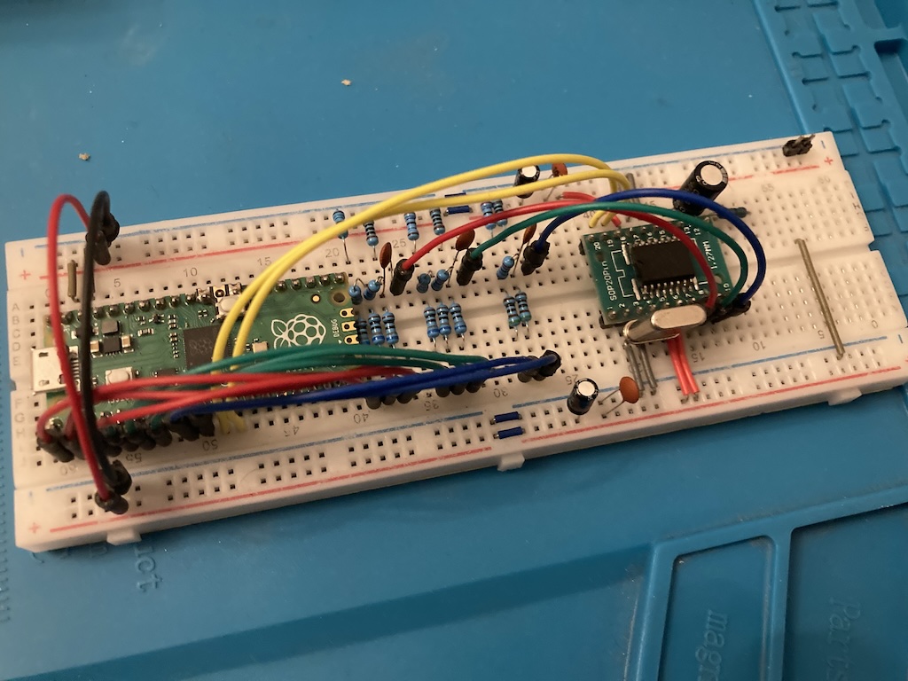
The Pico dominates the left hand side of the breadboard, with 8 sets of coloured wires connecting the 8 pixel output pins to their respective resistor ladders. There are two extra wires, white for vsync, and grey for hsync. I’ve also added a 1N5817 Schottky Rectifier Diode for power protection in case you want to power this circuit from an external 5VDC supply whilst having it connected to your computer via USB.
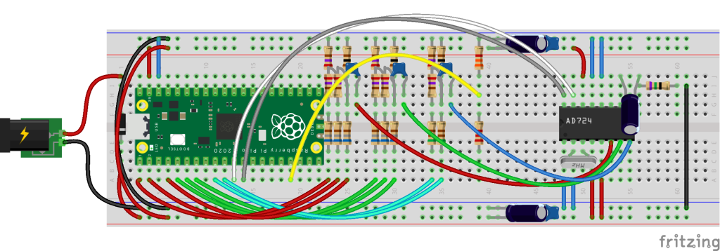
I would have liked to have implemented this using through-hole components, but could only get an AD724 at the time in a SOP-16 package, so had to solder that to an adaptor. You can probably make out the three sets of resistor ladders in the middle of the breadboard, and the AD724 is at the end.
The chip requires separate power for the digital and the analogue sides, and there are two pairs of smoothing capacitors thrown in.
The composite video connection is made by connecting the centre of the coaxial to the right pin of the rightmost resistor in the picture, and ground is the next pin along, courtesy of the long black wire.
The Software
As mentioned, the Pico-mposite software had already been tweaked in anticipation of a colour version. All this does is configure which pins are used for outputting the luminance values, and the horizontal and vertical sync. The rest is fairly agnostic; the monochrome version just drives 5 pins for luminance rather than the combined 8 for the colour version. There is an option in opt_colour that determines which version is compiled.
The Results
I was testing this on an old LCD TV; there is some dot-crawl still, which could be down to it running on a breadboard, or more likely, the timing being a bit out in the PIO. Yet on the whole I’m happy with that for a first attempt.
