Composite Video Modification
I mentioned in a previous post that I was going to modify my Spectrum to output composite video out of its TV port rather than a modulated RF signal. I take absolutely no credit for this; I discovered the instructions on Womble’s Retro Repair Shack, who in turn credits an article in the magazine “Crash” from 1986 (possibly Issue 28).
To understand why this modification is necessary, a short history lesson is required. Back in the day TVs lacked inputs. The typical home set probably just had an RF IN socket for the aerial feed. Devices such as video recorders and home computers were therefore designed around this restriction. The device, in this case a Sinclair Spectrum, would output a modulated RF signal that the TV could tune into. More expensive computers, such as the BBC, would also have a monitor output.
This is how it works. The Spectrum video circuit produces a composite video signal. This is fed into the modulator which converts that into an RF signal. This is fed into the back of the TV set via a coaxial cable. The TV then demodulates the RF signal back to a video signal and then displays it.
Clearly there are a couple of stages that can be eliminated in this age of TVs with multiple inputs, including composite video. This simple modification bypasses the Spectrum modulator and feeds the composite video signal from the motherboard directly to the TV out on the Spectrum.
To perform this, you will need a fine tipped soldering iron, solder, a cross-head screwdriver, a solder sucker and a small pair of long nosed pliers.
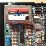
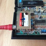
First, remove the keyboard to expose the Spectrum motherboard, The modulator is the large silver box at the top-left of the board. This modification converts the RF socket on the modulator to a Composite Video socket; the sockets for both are identical.
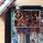
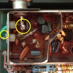
The top of the modulator just unclips. Once removed, you should be able to see a resistor in a plastic sheaf (circled) which is soldered to the centre pin of the video out socket.
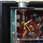
Carefully unsolder the resistor and bend the resistor leg down, making sure it is not touching anything inside the modulator.
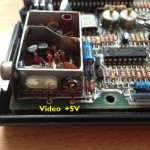
There are two pins to the left of the modulator; the left one is the composite video feed, the right one is the power feed.
The +5V wire is soldered to the top of the motherboard and the Video feed is soldered through. Carefully unsolder both connections and bend them out of the way.
The modulator is now disconnected from the circuit.
If you decided to retain the wires then I would suggest either wrapping them in heat shrink or, as I have done, applying a small blob of glue from a glue gun to prevent them from shorting on the modulator case, which is grounded.
Finally, connect the composite video feed from the motherboard to the centre pin of the TV out socket in the modulator. Thankfully the modulator has a spare hole you can poke this wire through. I used a piece of thin insulated single core wire to make the connection.
Check that there are no obvious shorts, remembering that the modulator case is grounded, then replace the modulator top and test. You can use a standard composite video cable now to connect your Spectrum to your TV; the RF socket on the Spectrum is the same size as a composite video socket.
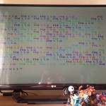
This will give your Spectrum a new lease of life. Not only does it provide a much more stable image on screen but it is much easier to connect to modern TVs and monitors.
This procedure took me about an hour from beginning to end and in my opinion is possible for anyone who is reasonably comfortable with a soldering iron. It is also fairly easy to revert the Spectrum back to factory conditions; simply remove the wire and reconnect the modulator. I’m not entirely sure why you’d want to do that though!

