
Homebrew Z80 Computer (Part 6)
In Part 4 of this series I implemented a proper clock signal using a crystal and logic, in readiness for adding the TMS9918 video chip into the circuit. This provides a 5.37Mhz clock signal for the Z80, along with a 10.738Mhz signal for the video chip, and boosted the Z80 clock speed over fivefold from the original ~1Mhz the 555-timer based clock.
However, I discovered this caused comms instability with the software UART I’d implemented in the STM32; it could not, as a device, read or write bytes to the Z80 data bus quick enough at the higher CPU clock speeds. To resolve this I’ll need to use a hardware UART.
If you like what I’m doing, you can help support this project by contributing to my Ko-Fi page.
What is a UART
A UART, or Universal Asynchronous Receiver/Transmitter is a computer chip that is designed to convert parallel data into a serial bit stream and transmit that data over a single wire. They contain a shift register that converts bytes to a bitstream, and vice versa, along with control logic to ensure that the CPU knows when it is safe to write or read data in the UART. Typically 2 data lines are needed; a transmit (TX) and receive (RX), so that data can be sent and received at the same time, though extra wires can be used for flow control: CTS – Clear to Send and RTS – Request to Send.
There are usually two UARTs cross-wired – TX <–> RX and CTS <–> RTS. I’ve not bothered with CTS and RTS at this point.
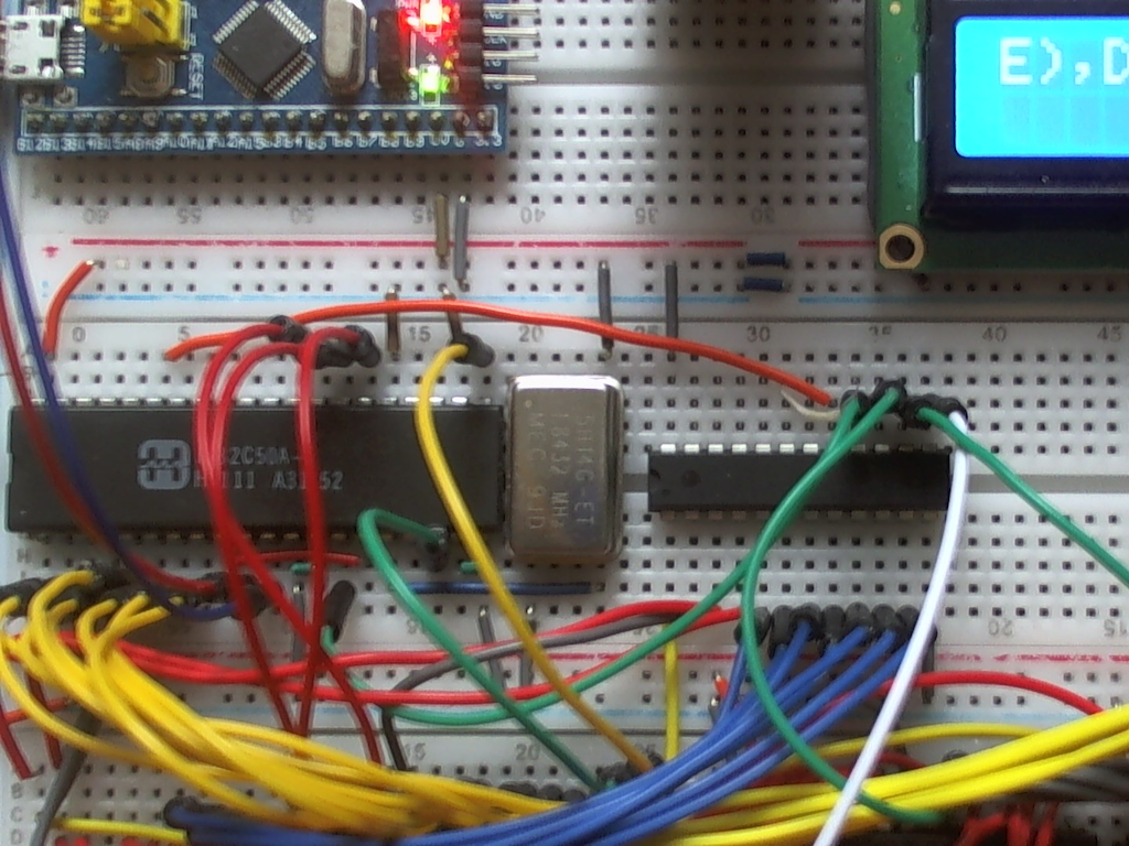
In the BSX, the first UART is within the STM32 itself. The second is an 8250 UART IC mounted on the breadboard that is connected to the Z80 on the data bus.
The 8250 UART
The 8250 and 16550 UART chips are similar in function and pinouts. The only difference is the 16550 has an internal buffer of 14 bytes, whereas the 8250 has a single byte buffer. The only reason I went with the 8250 is that I managed to get hold of a cheap one off eBay. The buffer size is irrelevant for this project.
The 8250 requires 7 I/O addresses, and is mapped using the GAL (added in Part 5) to the address space &80 to &87. The GAL has been configured to provide an active low chip enable (CE) line, and a reset line that is derived from the Z80 reset but inverted.
The UART requires a 1.8432Mhz external clock signal to provide standard baud rates; this provides a maximum rate of 115200 baud, which is divided down internally to provide other common baud rates. That can be provided by a crystal or oscillator package.
Bill of Materials
- 1 x 82C50A UART
- 1 x 5H14ET 1.8432Mhz 14 pin TTL Oscillator (or similar)
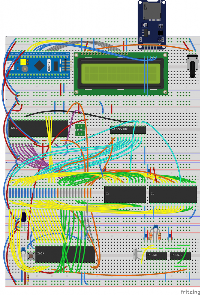
Schematic

Changes
There are some significant changes to the hardware and firmware:
- The UART is connected to the Z80 lines WR, RD, A0, A1, A2 and D0 to D7
- The UART clock signal connected to the 1.8432Mhz Oscillator
- The UART chip select and reset connected to the GAL
- The UART RX and TX connected to PB10 and PB11 of the STM32
- The GAL has an additional connection from the Z80 reset line; this is inverted in the GAL for the UART reset
- All connections to the Z80 from the STM32 are now redundant and have been removed
- The clock circuitry from Part 4 has replaced the 555 clock circuit to up the Z80 CPU speed from ~1Mhz to 5.37Mhz
- A new STM32 sketch is required to send and receive data to the UART from the STM32 via Serial3 (PB10 and PB11)
- The Z80 ROM has been updated to transmit and receive data via the UART rather than the STM32
Full schematics and software can be downloaded here from my BSX GitHub account.
The pins PB10 and PB11 of the STM32 are 5V tolerant. As the UART is TTL, if you use another microcontroller, like an Arduino, you may need a level shifter to 3.3V to avoid damage. It’s important to note that although they can handle 5V, TX outputs 3.3V. This is fine and within TTL specs.
Programming the UART in Z80
The UART is fairly straightforward to set up; a handful of lines of Z80 code is sufficient to configure it.
First, define some port addresses. In the BSX, the port has been mapped to addresses 0x80 to 0x87.
UART_PORT:		EQU	0x80		; UART Z80 port base address

; Some of the ports have more than one use
;
UART_REG_RBR:		EQU	UART_PORT+0	; Receive buffer (read)
UART_REG_THR:		EQU	UART_PORT+0	; Transmitter holding (write)
UART_REG_DLL:		EQU	UART_PORT+0	; Divisor latch low (when bit 7 of LCR is 1)
UART_REG_IER:		EQU	UART_PORT+1	; Interrupt enable
UART_REG_DLH:		EQU	UART_PORT+1	; Divisor latch high (when bit 7 of LCR is 1)
UART_REG_IIR:		EQU	UART_PORT+2	; Interrupt identification
UART_REG_LCR:		EQU	UART_PORT+3	; Line control
UART_REG_MCR:		EQU	UART_PORT+4	; Modem control
UART_REG_LSR:		EQU	UART_PORT+5	; Line status
UART_REG_MSR:		EQU	UART_PORT+6	; Modem status
UART_REG_SCR:		EQU 	UART_PORT+7	; Scratch register
A lookup table of common baud rates:
; Common baud rates
; These are all factors of the chip's baud rate when clocked at 1.8432Mhz (115200)
;
UART_BAUD:		EQU	115200		; Chip baud rate when divisor = 1

UART_BAUD_1200:		DW	UART_BAUD/1200
UART_BAUD_2400:		DW	UART_BAUD/2400
UART_BAUD_4800:		DW	UART_BAUD/4800
UART_BAUD_9600:		DW	UART_BAUD/9600
UART_BAUD_14400:	DW	UART_BAUD/14400
UART_BAUD_19200:	DW	UART_BAUD/19200
UART_BAUD_38400:	DW	UART_BAUD/38400
UART_BAUD_57600:	DW	UART_BAUD/57600
UART_BAUD_115200:	DW	UART_BAUD/115200
And a routine to initialise the UART:
; HL: Address in baud rate table
;  A: Flow control bits
;
UART_INIT:		AND	0x7F				; Clear the DLAB bit
			PUSH	AF				; Stack the flow control bits
			LD	A,(HL)				; Fetch the divisor values from the baud rate table
			INC 	HL
			LD	H,(HL)
			LD 	L,A
			LD	A,0x00: OUT (UART_REG_IER),A	; Disable interrupts
			LD	A,0x80: OUT (UART_REG_LCR),A 	; Turn DLAB on; ports 0 and 1 are now the divisor registers
			LD	A,L:	OUT (UART_REG_DLL),A	; Set the divisor low byte
			LD	A,H:	OUT (UART_REG_DLH),A	; Set the divisor high byte
			POP	AF:	OUT (UART_REG_LCR),A	; Write out flow control bits and turn DLAB off
			RET
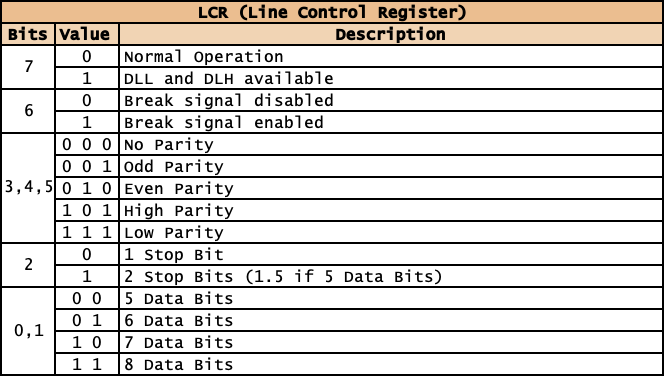
By setting bit 7 of register LCR in line 7 we change the behaviour of ports &80 and &81 so that we can configure the baud rate in lines 11 and 12 by setting a divisor value. The baud rate is a division of the UART maximum baud rate. All the common baud rates are factors of that, so for 9,600 baud, the divisor is 12 (115200/9600). I use a lookup table to get those values and pass the function UART_INIT the address of the baud rate I want. For example:
			LD	HL,UART_BAUD_9600	; 9600 BAUD
			LD	A,0x03			; 8 data bits, no parity, 1 stop bit
			CALL	UART_INIT
The flags passed in A to configure the line control register are:
This routine will queue a byte in the UART transmit holding register
; A: Data to write
; Returns:
; F = C if written
; F = NC if timed out
;
UART_TX_WAIT		EQU	1024				; Count before a TX times out

UART_TX:		PUSH	BC				; Stack BC
			PUSH	AF 				; Stack AF
			LD	B,low  UART_TX_WAIT		; Set CB to the transmit timeout
			LD	C,high UART_TX_WAIT
1:			IN	A,(UART_REG_LSR)		; Get the line status register
			AND 	%00100000			; Check for TX empty
			JR	NZ,2F				; If set, then TX is empty, goto transmit
			DJNZ	1B: DEC	C: JR NZ,1B		; Otherwise loop
			POP	AF				; We've timed out at this point so
			POP	BC				; Restore the stack
			OR	A				; Clear the carry flag and preserve A
			RET
2:			POP	AF				; Good to send at this point, so
			OUT	(UART_REG_THR),A		; Write the character to the UART transmit buffer
			POP	BC				; Restore the stack
			SCF					; Set the carry flag
			RET
And this routine will read a byte from the UART receive buffer register
; A: Data read
; Returns:
; F = C if character read
; F = NC if no character read
;
UART_RX:		IN	A,(UART_REG_LSR)		; Get the line status register
			AND 	%00000001			; Check for characters in buffer
			RET	Z				; Just ret (with carry clear) if no characters
			IN	A,(UART_REG_RBR)		; Read the character from the UART receive buffer
			SCF 					; Set the carry flag
			RET
This page contains more details on the UART registers.
Programming the UART on the STM32 / Arduino
It’s even easier setting up the UART within the Arduino sketch:
void setup() {
	Serial.begin(9600);	// Setup the comms between the PC and the STM32
	Serial3.begin(9600);	// Setup the comms between the STM32 and the 8250 UART
}
The STM32 is now just responsible for powering the BSX and relaying communications from the PC terminal (i.e. PuTTY) to the UART, and vice versa. To achieve that, this code snippet is use in the loop:
void loop() {
	byte b;
	if(Serial.available() > 0) {		// Has the PC sent any data?
		b = Serial.read();		// Read a byte from the STM32 UART
		Serial3.write(b);		// Relay it to the Z80 UART
	}
	while(Serial3.available() > 0) {	// While the Z80 is sending data
		b = Serial3.read();		// Read a byte from the 8250 UART
		Serial.write(b);		// Relay it to the STM32 UART
	}
	delay(1);				// Short delay to slow comms down
}
If the delay is removed, I’ve found that comms become a bit garbled with missing characters; the STM32 is running 13 times faster than the Z80, and the UART does not have a receive buffer, so gives the Z80 a chance to process the characters in a timely fashion.
What’s next
Now I’ve got a reliable clock on board and the comms are working fine with the UART, it’s time to get the video output working.