Homebrew Z80 Computer (Part 4)
The computer is now a fully operational Z80 board, with ROM, RAM and I/O. All I/O is through a serial USB connection to a terminal package (such as PuTTy), and there is some software on ROM, my Z80 monitor program, and BBC Basic for Z80.
It is still running on a slow (~1Mhz) clock provided by the clock circuit devised in Part 1.
The next step is to implement a faster and more accurate clock signal. This will be required by the video circuit I’m planning on implementing in the next stage.
Clocks
The most common way of generating a clock signal is by using a crystal oscillator. These contain a piezoelectric material that is tuned to resonate at a specific frequency, and are the main component in a quartz crystal oscillator (XO) circuit.
It is possible to buy these as a complete circuit in a four-pin package. I decided to use a two-pin crystal oscillator, partly because four-pin oscillators of the required frequency are expensive, and partly to familiarise myself with oscillator circuits.
The frequencies I require are:
- 10.738633Mhz for the TMS9918 video chip clock
- At least 3.5Mhz for the Z80
10.738633Mhz crystals are quite expensive, so I decided to buy some 21.47727Mhz crystals instead. These are exactly double the required frequency, so the plan will be to divide the frequency by 2 for the TMS9918 video chip clock, and divide again for the Z80, giving me a respectable 5.369Mhz clock.
Parts List
1 x Crystal Oscillator
2 x 330Ω Resistors
1 x 22pF Ceramic Capacitor (load capacitor) *
1 x 74LS04 Hex Inverter (6 NOT gates in a DIP package)
1 x 74LS74 Dual JK Flip Flop (used to divide the clock frequency down twice)
2 x 100nF Ceramic Capacitor (decoupling capacitors for the logic chips)
1 x TMS9918 video chip (will be part of my BSX video circuit)
NB: I originally chose a much lower value for the load capacitor, I think 10pF.
The Oscillator
I’m unfamiliar with this type of circuit, so spent a while researching it on the Internet before I arrived at a design I though would work.
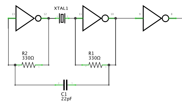
I ended up on this page, and decided to try to build a series resonant oscillator circuit.
As you can see, it’s a fairly straightforward circuit.
When I tested this on the scope, by measuring the signal on Pin 8 of the 74LS04, I felt quite chuffed; there was a waveform on the screen.
However, on closer analysis, the frequency measured was too high, over 29.3Mhz on average.
I’m still trying to get my head around how this circuit works. I think it is an amplifier with feedback, and the logic gates are there to be the amplifier, and square the sine waves.
The third logic gate on the output is a buffer, to isolate (to some extent) the output from the amplifier.
It was suggested on Twitter that the load capacitance value was probably too low, and that is was only working due to the parasitic capacitance of the breadboard.
I decided to fix that later; it was at least oscillating.
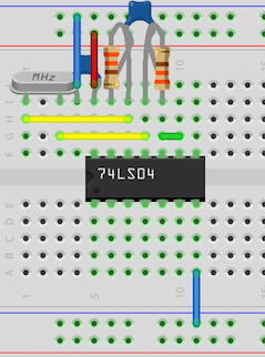
The Circuit 
Testing… 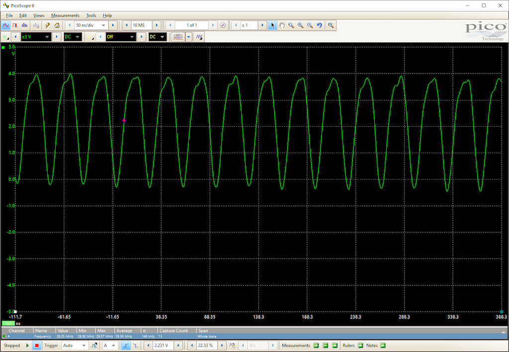
Oscillating too fast
Dividing the clock frequency
I’m using a 74LS74 dual flip-flop to divide the frequency down by passing the clock signal through it twice. The input is connected to the final output of the 74LS04, and provides two additional clock frequencies.
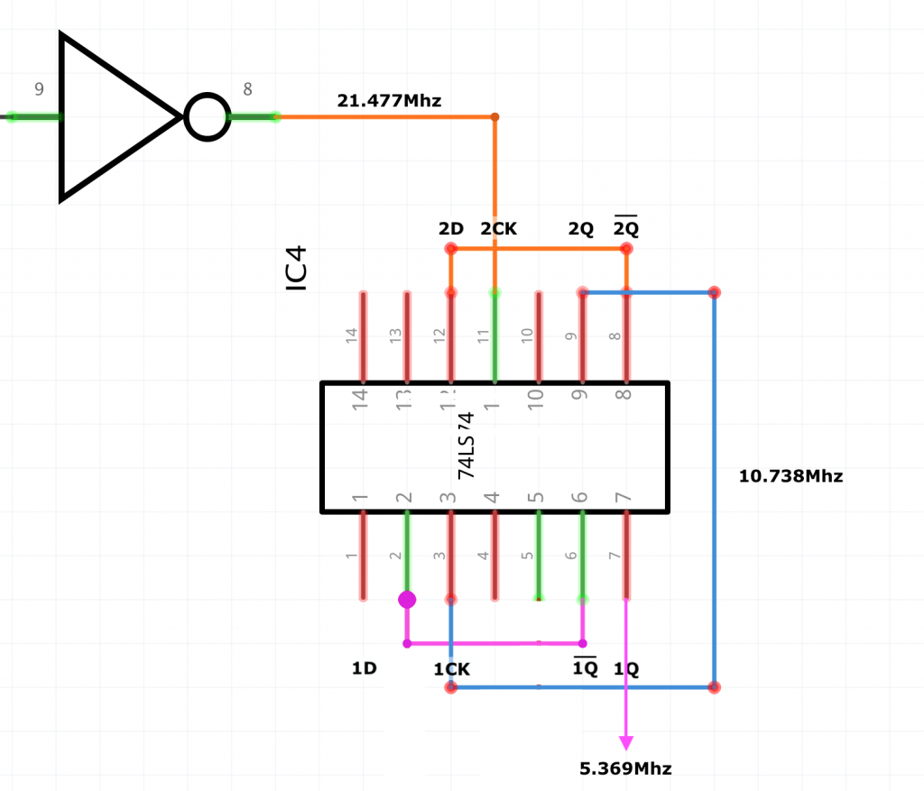
- The input clock signal from the oscillator is connected to 2CK
- The output /2Q is fed back into 2D
- The output 2Q is half the input clock frequency (10.738Mhz)
The divided clock signal can be divided again by 2 by feeding it (2Q) into the other half of the flip-flop.
- The input clock signal 2Q is connected to 1CK
- The output /1Q is fed back into 1D
- The output 1Q is half the frequency of 2Q (5.369Mhz)
2Q and /2Q will be used as the clock signals for the TMS9918 and 1Q may be used at a later date as a clock for the Z80.

The circuit 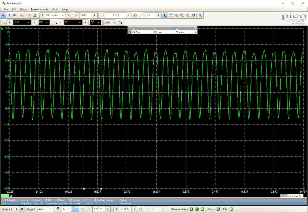
Original frequency 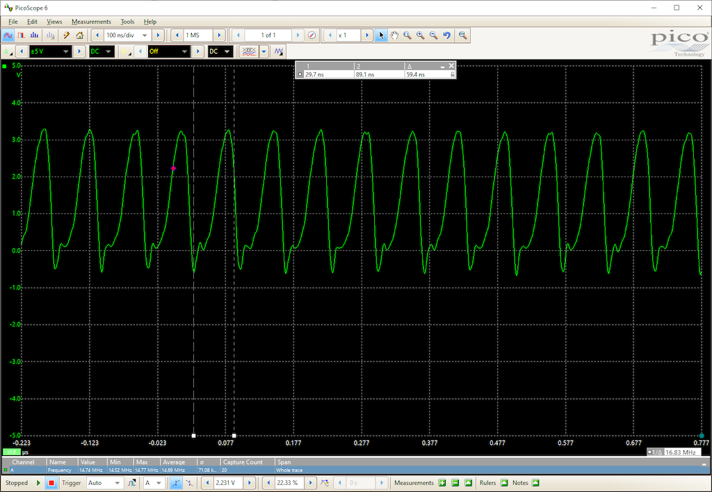
Divided by 2… 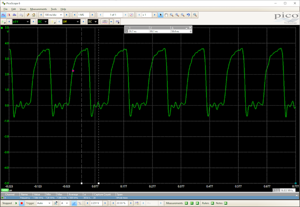
…And by 2 again
Connecting the TMS9918
Before I connected the TMS9918, I needed to sort out the fast clock speed noted at the beginning of this article. The fix proved to be fairly straightforward; increasing the value of the load capacitor (to 22pF) until it started resonating at the correct frequency.
The TMS has two clock input pins; on pins 39 and 40, lablled XTAL1 and XTAL2 (Pin 40). I think the designers expected a 10.738Mhz crystal to be placed across these.
To drive these from this circuit, I need to connect a 10.738Mhz clock signal to one of those pins, and the inverted clock signal to the other. Thankfully our divider has those on 2Q and /2Q.
Testing
To test, I’ve connected just the power and clock signals to the chip.
The one I purchased off eBay is not a new chip, and has probably been recovered from a board, so there is a fair chance it’s a dud.
The TMS9918 divides its input clock frequency down by 3 internally, and outputs a 3.579Mhz clock on Pin 38 (CPUCLK). I assume this is to help reduce chip counts; it’s perfect for driving the CLK line of the Z80.
This seems like a good signal to test.
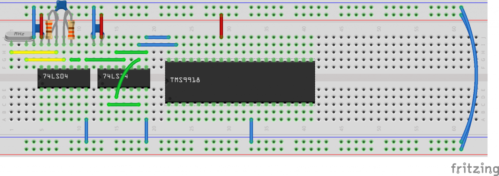
Completed circuit 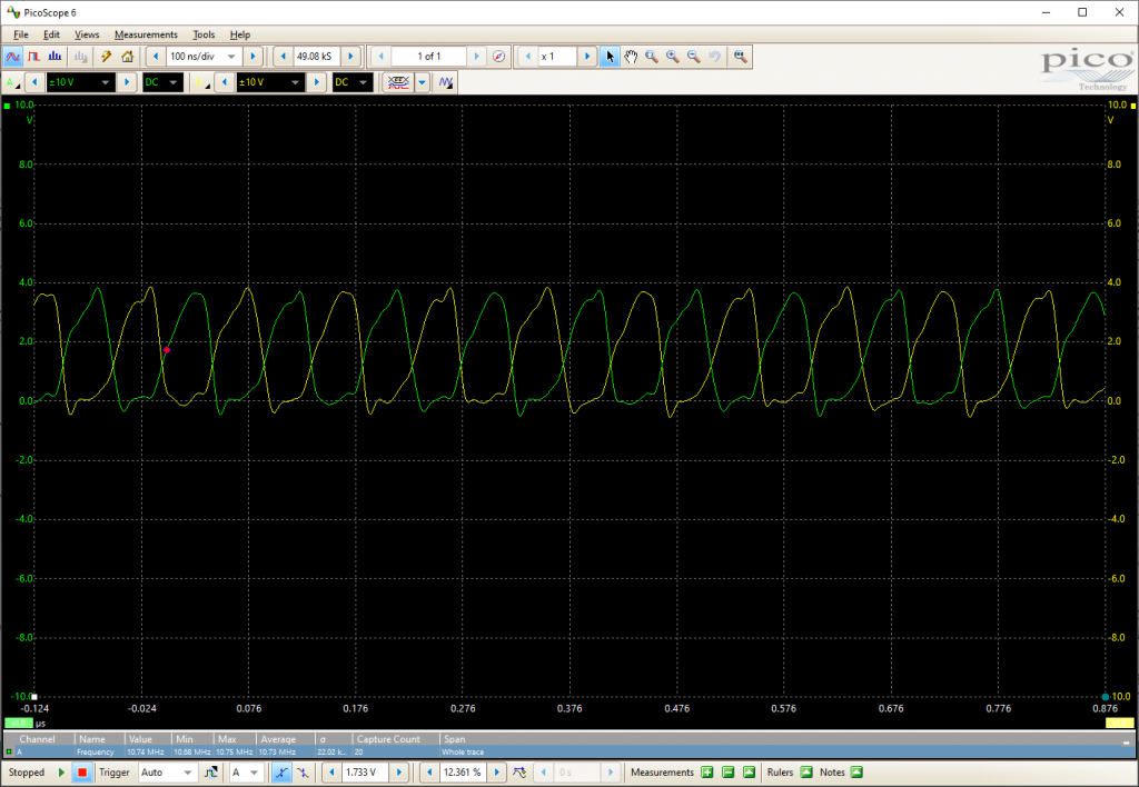
Input clock signals 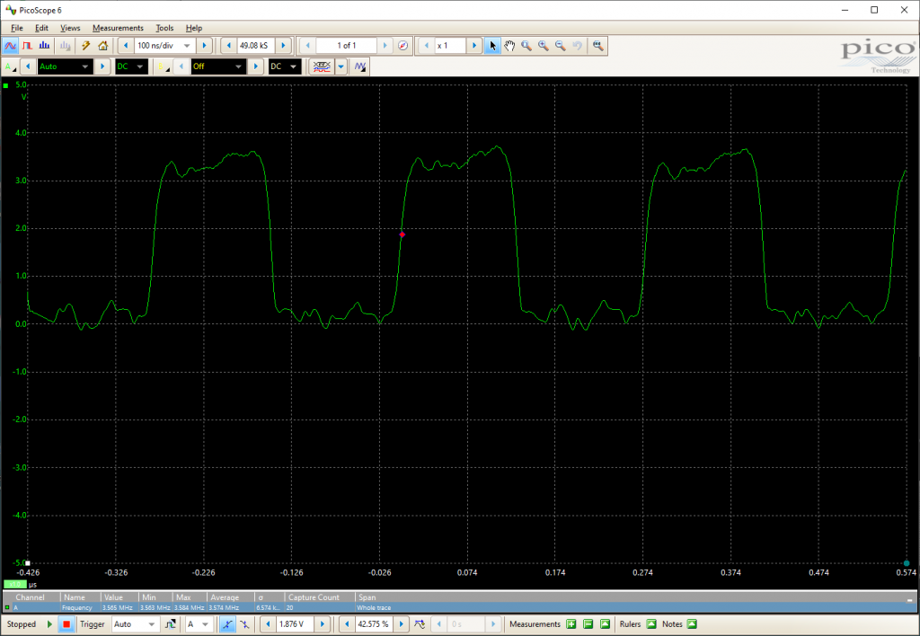
CPUCLK signal from TMS9918
Thankfully my chip seems to be doing something – I’m getting a fairly solid 3.574Mhz signal off that pin.
I will probably use this clock signal to drive the Z80, with an option to boost up to 5.369Mhz using 1Q.
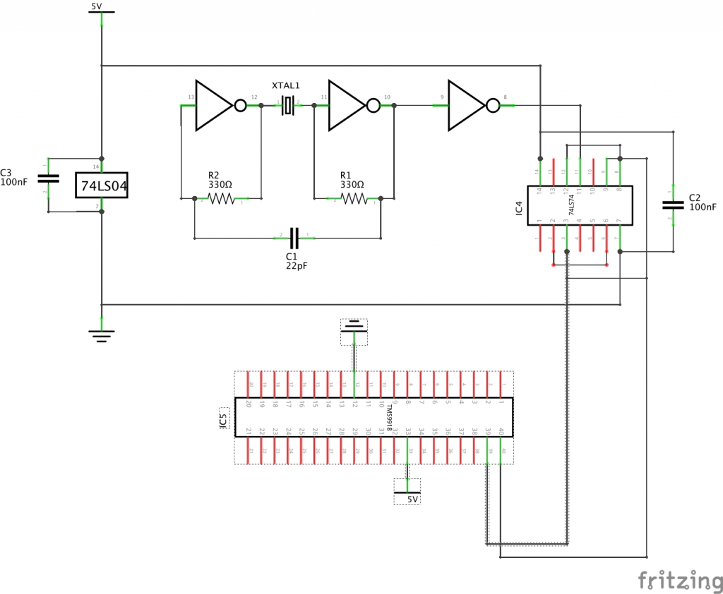
Schematic
NB:
- I use 3 NOT gates from the 74LS04; two are used in the oscillator circuit, the third is used as a buffer.
- The TMS9918 should really have a decoupling capacitor on the power rail, fine for testing purposes though.
Footnote
I tried connecting the Z80 to the TMS9918 CLK signal, and it worked fine. However, the much faster clock rate proved too much for the STM32; it was unable to drive the data bus at that speed, so was outputting gibberish over the USB serial.
I’ve had this before, when I increased the Z80 clock speed to ~1Mhz, and spent a day or so refactoring the STM32 code so that it could handle the I/O interrupt faster. I suspect I’ve taken that code as far as I can, so rather than plumbing the STM32 directly to the Z80 bus and expecting it to act as a peripheral chip, I’ll be putting in an 8250 UART to handle the serial comms between the Z80 and PC.
I may still connect the serial comms via the STM32 as a interim step, as it is useful for power, and drives the built-in LCD display. And it may come in handy for handling other peripherals such as keyboards.
The next steps are:
- Add the UART and connect it between the Z80 and STM32
- Add more logic to decode the address lines for the UART and other peripherals (done – see part 5)
- Modify the Z80 ROM code to read and write data through the UART
- Start the TMS9918 video circuit (Video RAM, decode logic)
