
Composite Video Modification for the ZX81
A few years back I attempted this mod on a Spectrum, based upon an old magazine article I’d stumbled across on the Internet. A link to my mod (with links to the original article) can be found here.
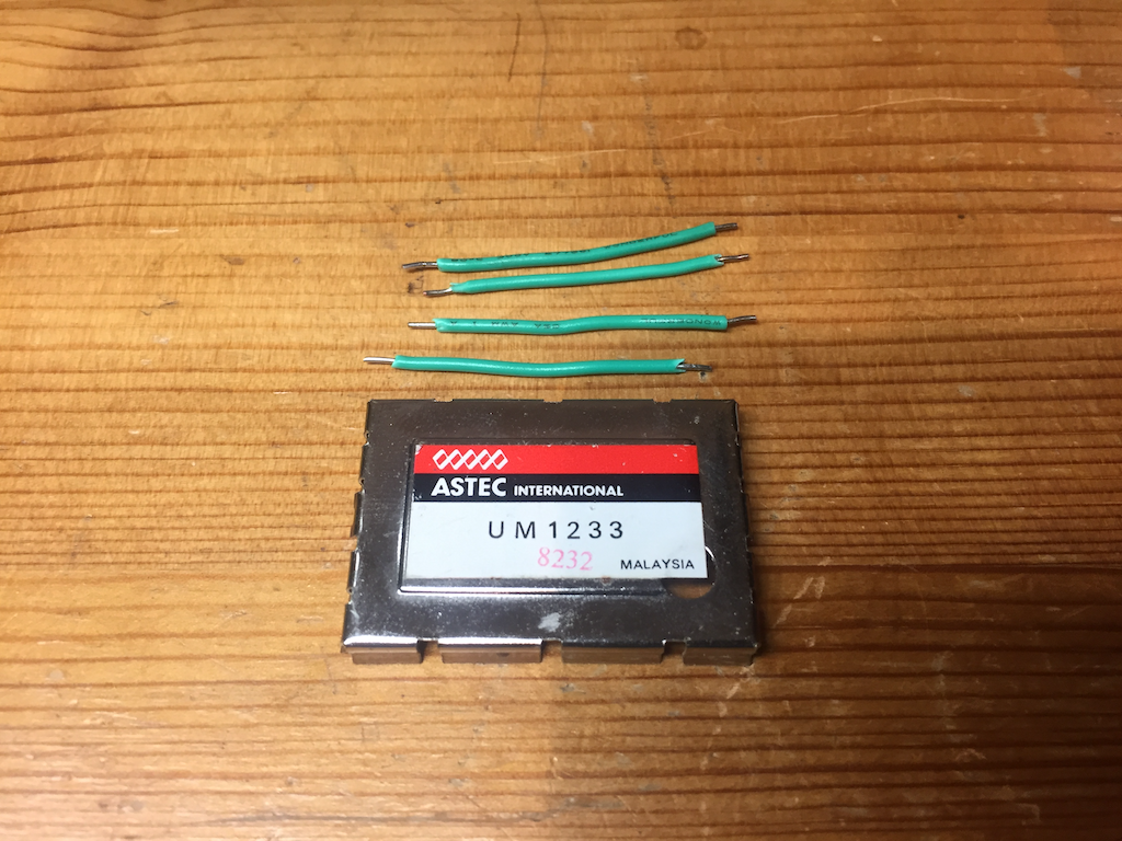
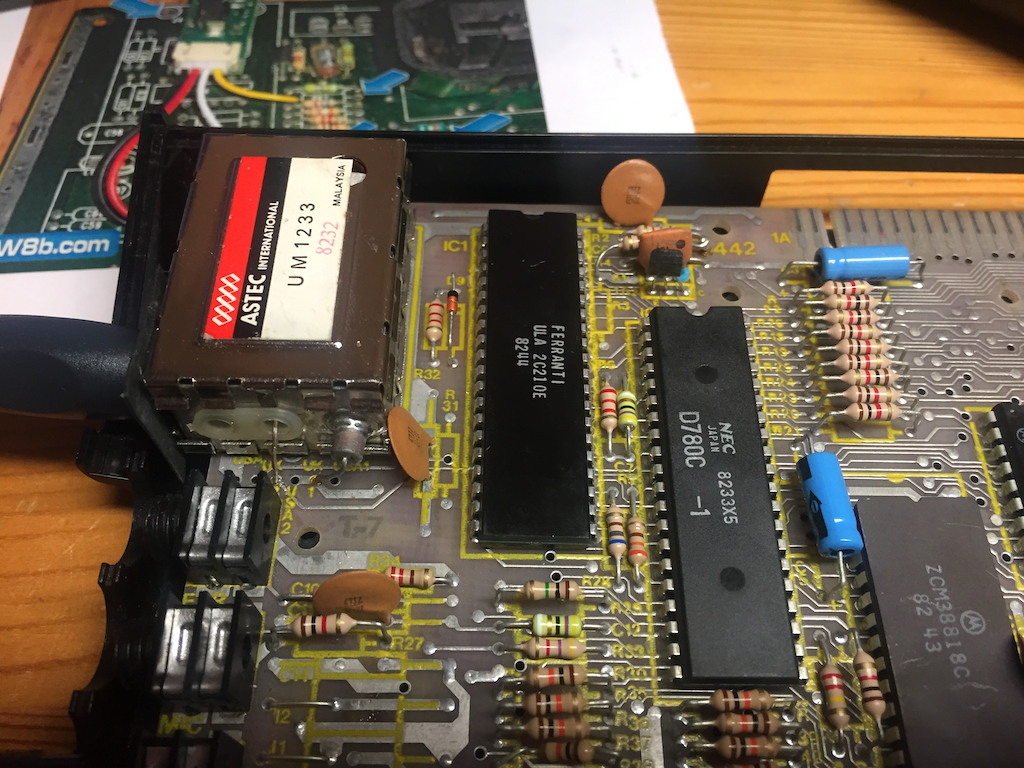
The ZX81 video circuitry is driven directly by the ULA and, like the Spectrum, that signal is fed into a UHF modulator which converts the composite signal into an RF signal that a TV can tune into.
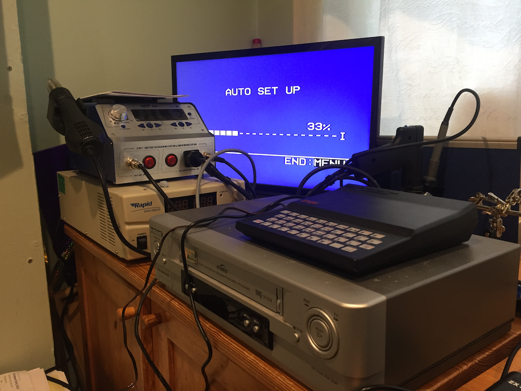
My portable Samsung LCD TV refused to tune into the ZX81.
I’d determined that the ZX81 was working by tuning it into an old VCR I have knocking around for this kind of thing, and plugging that into the TV via SCART. This is obviously not a long-term solution, so decided to convert my ZX81 over to composite.
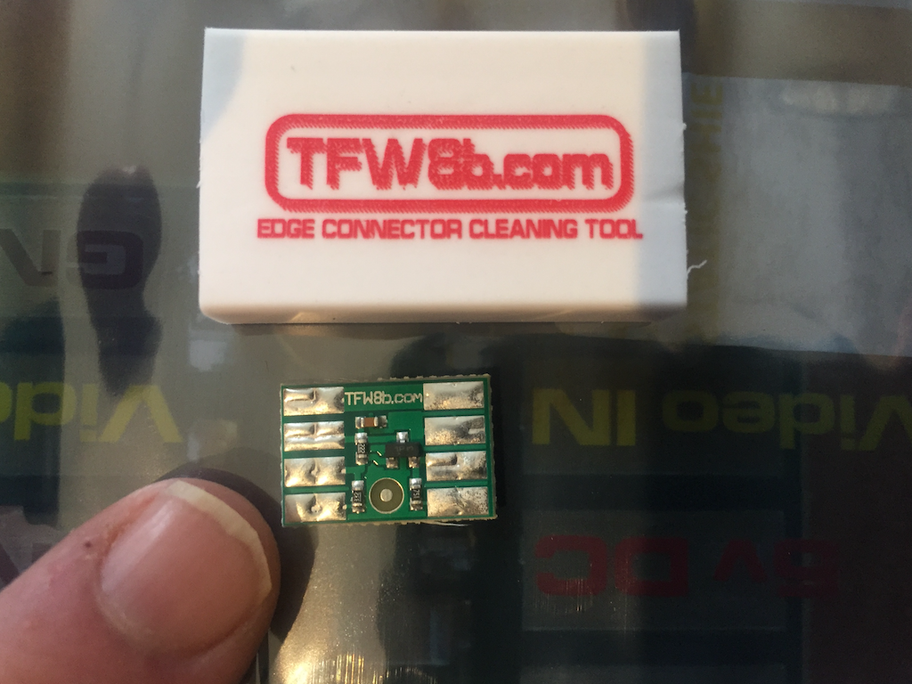
The modification I attempted is based upon one suggested by Tynemouth Software, and requires an amplifier / buffer board – I used the one suggested in the article by The Future was 8 Bit. So there is nothing new to be learned from this article, other than my experiences as a layman.
Please note that my ZX81 has the later modified ULA (210E) – if your ZX81 has the buggy 184E ULA then your mileage may vary with this – that ULA does not properly implement a back-porch after the line-sync signal, so the picture may be dark. There are alternative boards which resolve this issue by inserting a back-porch into the signal.
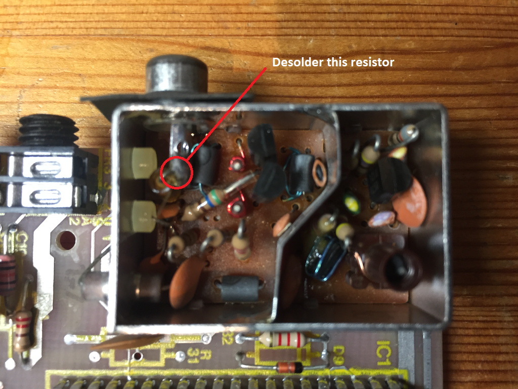
So the first step is to take the lid off the modulator, desolder the component lead connected to the modulator pin, bending the component out of the way.
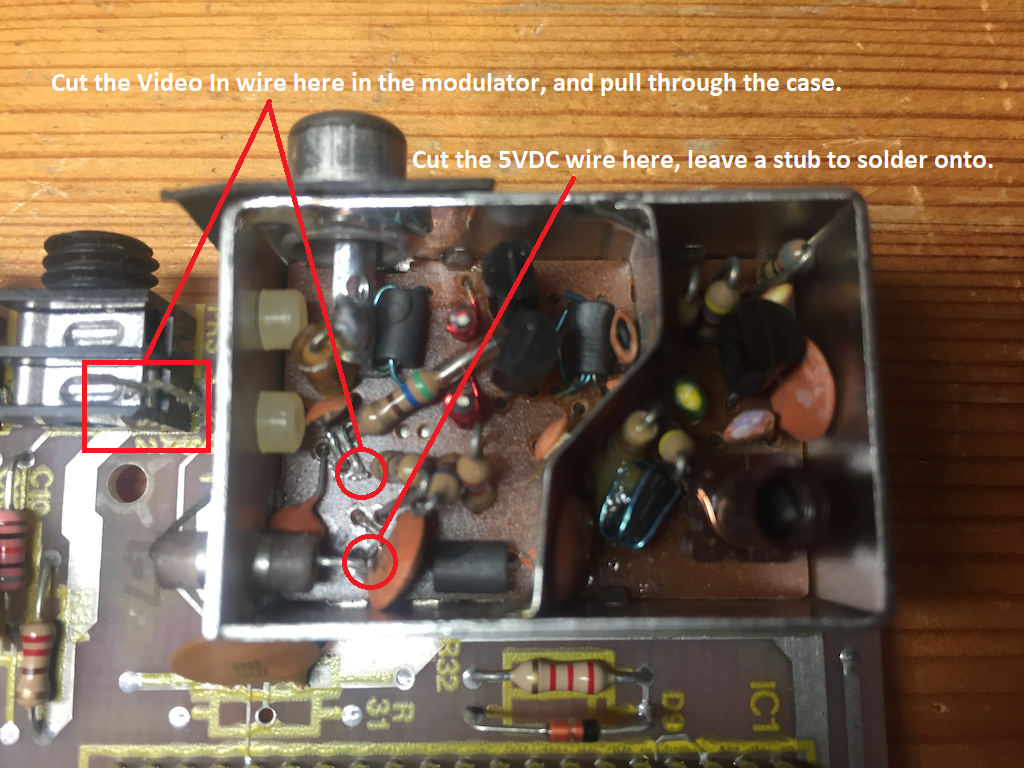
Then, remove the composite input wire – cutting it out of the modulator, desoldering it from the motherboard and pulling the wire out through the grommet on the modulator case.
Finally, cut the 5VDC power wire inside the modulator case – try to keep that as long as possible; we’ll be lengthening that later.
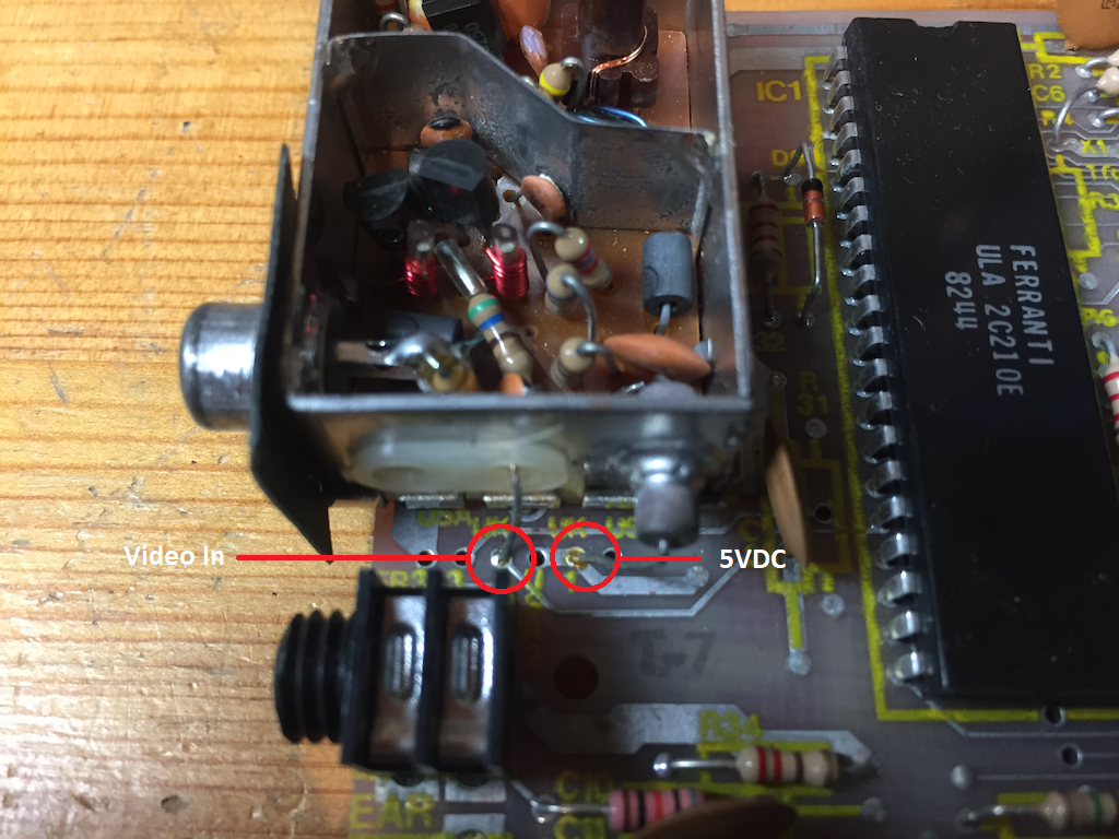
Next – find some single-core wire, preferably thicker than wire-wrap (30AWG), but not too thick; we’ll be bending these wires around later to fit in the modulator case. I found that cutting the four wires needed to be about the length of the modulator case worked, possibly slightly longer for the wire that will be soldered from the Video Out on the board to the connector pin.
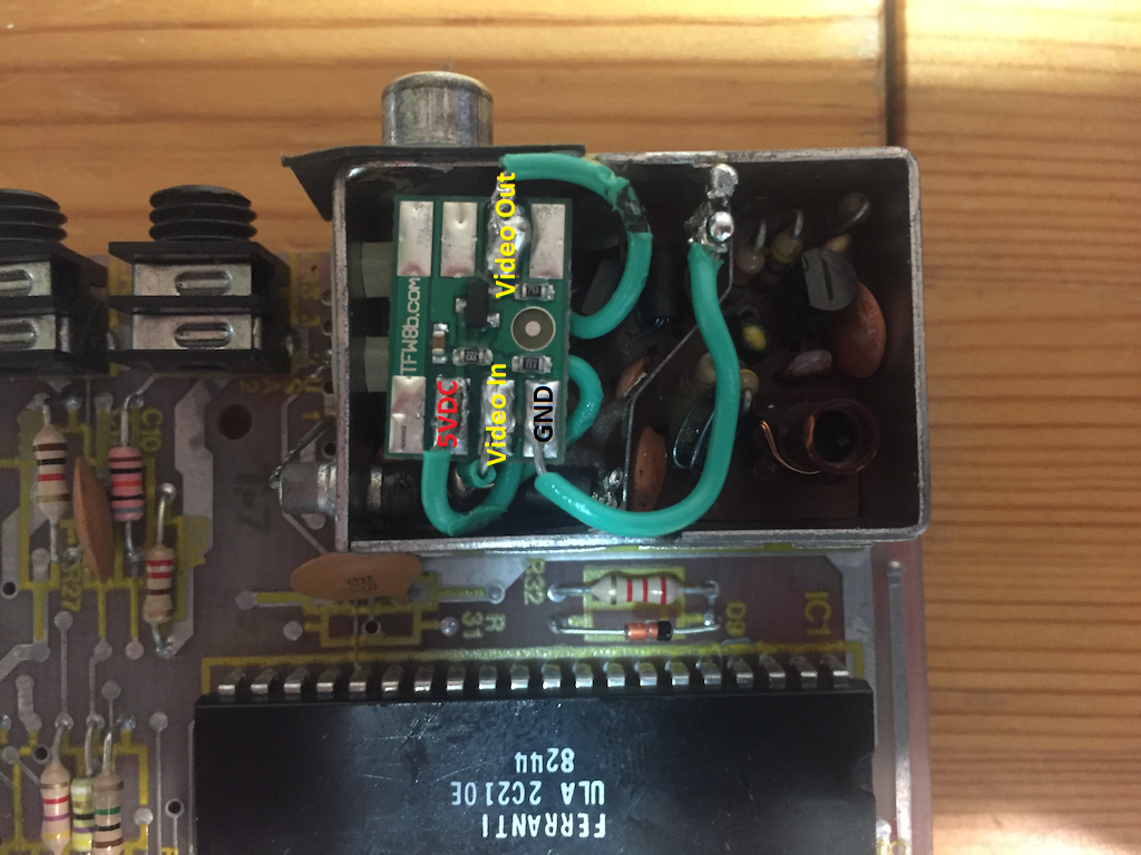
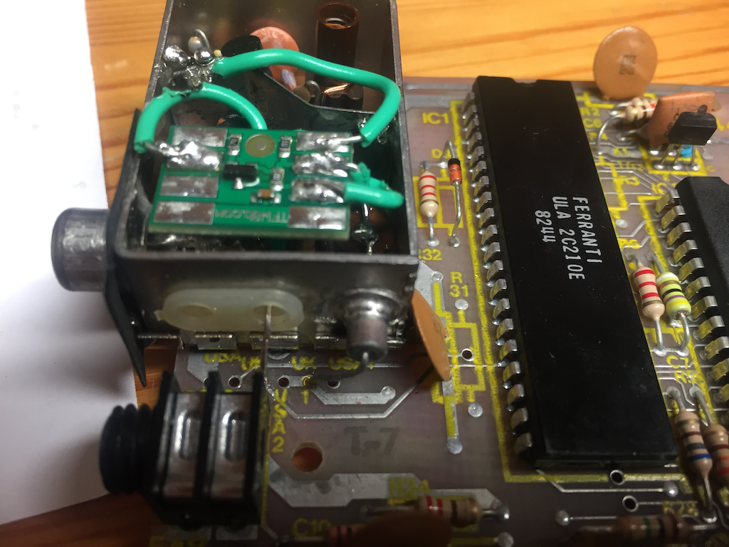
So solder the wires onto the board, making sure the orientation is correct. The board does get quite hot quickly when soldering the wires on, so don’t linger, and let the board cool down before soldering the next one on.
When fitting the board, I soldered the 5VDC wire first, as that was the fiddliest – wire-to-wire soldering is not my strongpoint. The second wire, the Video In, was poked out of the modulator through a grommet. I had to strip a lot of the insulation on this wire to fit it through the hole. That was then soldered onto the motherboard, taking care to solder it back in the same hole.
Next, the Video Out cable was soldered onto the modulator connector pin. Don’t make the mistake I first did of poking the wire through the hole on the connector pin; that will push against the composite video plug as you push it in and you won’t get a terribly good connection between the pin and the plug.
Finally the ground cable was soldered onto the modulator case. This was the trickiest for me – I was using lead-free solder for this and, despite best attempts to prepare the surface and tinning the wires, I could not get the solder to stick. I would suggest using a solder that contains lead, and make sure your soldering iron is quite hot. And if you have a soldering iron with a bevelled tip, I’d use that – I don’t think my pencil-tipped iron was passing enough heat through.
Testing is fairly straightforward; before I plugged it in I made sure that all the pads on the board were connected to the motherboard with a continuity meter, so 5VDC and Video In to the appropriate wires outside the modulator and Ground to the modulator case and any ground point on the board, for example the heatsink for the regulator. Finally, check the Video Out is connected to the modulator connector inner pin by poking a probe inside.
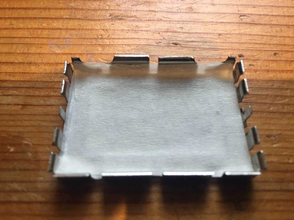
I put tape on the inside of the modulator lid to prevent any shorts if the board touched it – just a couple of layers of masking tap for now.
Finally, a quick test with the lid of the modulator off, and one with the lid on.
Footnotes:
I did have a lot of problems with this project – it was quite fiddly in places and I did struggle a bit at first getting the solder to stick. But lessons were learned, and if I were to do this again, I’d probably make a better job of it.
The video output is not quite composite level. It’s between 0.75V and 3V on my scope. This is better than the stock output from the ULA, which is between 1.5V and 3.75V. Most TVs should cope with this voltage fine. I think I’ve got an LCD TV (a Samsung model) that is particularly fussy about the video signal coming in. The picture is sometimes a little off when I plug my Spectrum in, with ghosting and odd colours. The ZX81 exhibits similar issues and sometimes no picture at all. I will need to investigate this further, and will update these articles when I find out more, but for the moment I’m going to leave that as a known issue.
Update: 26th January 2020
I did a little more testing to see whether it was my TV being fussy, or a fault with the repairs. I had my suspicions it was the TV, as the my Spectrum sometimes goes a bit fuzzy when plugged into it via composite video. So dug out an old in-car DVD player that has composite input and output.
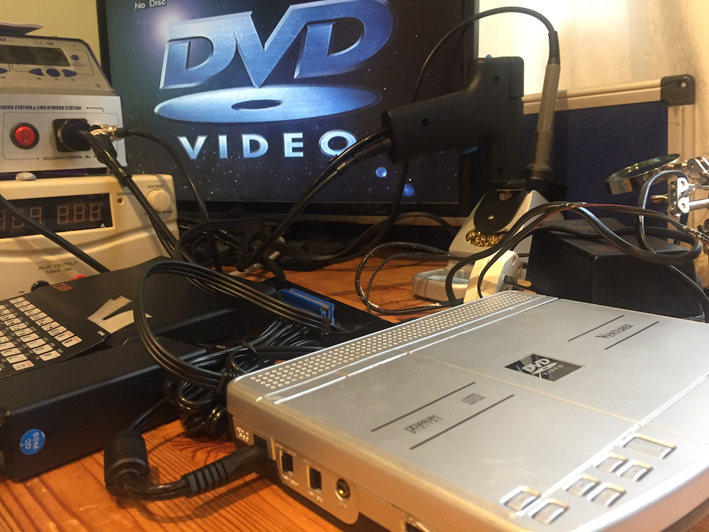
DVD player through TV 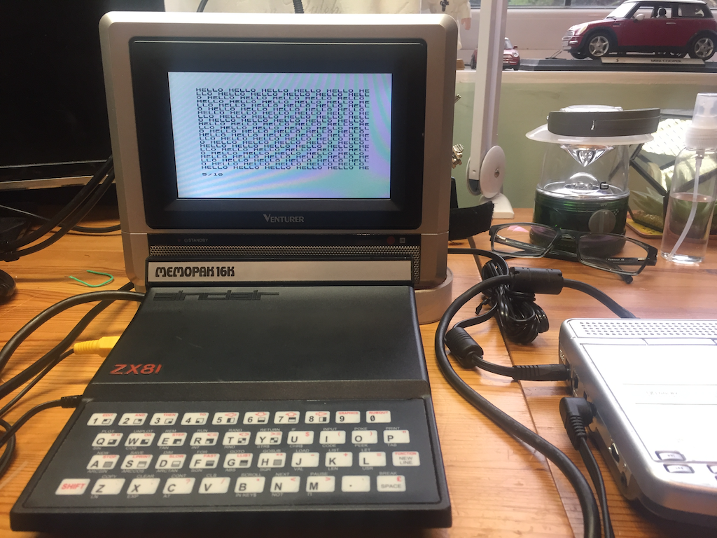
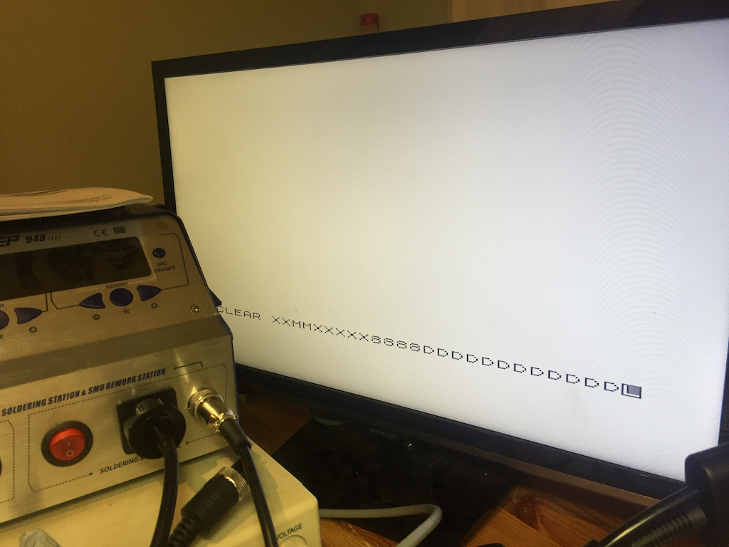
ZX81 through DVD screen
The in-car DVD player, which is outputting a near-textbook composite video output was rock steady on my TV, and the ZX81, plugged into the DVD composite video input was also rock steady. I can only conclude that the TV is just being very fussy about the voltage levels on the input. I was also quite taken by the look of the ZX81 connected to the DVD monitor – it looks perfect!