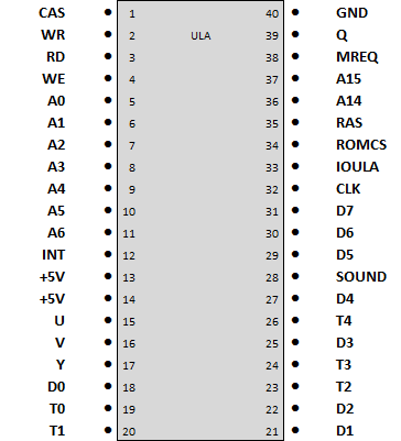
The Spectrum ULA was a custom gate array chip that handled the screen, beeper and paging in alternate ROM chips, such as the Interface 1.
ULA Pin Assignments
- A0-A6, A14-A15: Address lines
- D0-D7: Data lines
- U, V, Y: Video signals
- T0-T4: Keyboard data lines
- SOUND: I/O for the beeper
- Q: 14Mhz clock from the crystal
- CLK: Clock source to the Z80 (3.5Mhz)
- WR: Write
- RD: Read
- INT: Interrupt
- ROMCS: Rom chip select
- CAS: Column address strobe
- RAS: Row address strobe
- IOULA: ULA address select for IO port &FE
- GND/+5V: Power
ULA Operation
The ULA takes the clock feed from the crystal (14Mhz) and divides that down by 2 (7Mhz), then 2 again (3.5Mhz). The 14Mhz and 7Mhz clocks are used to drive the video and the 3.5Mhz clock is fed to the Z80.
The ULA will hold the CLK line high when it needs to access the video memory at the same time the Z80 does, so if you put an oscilloscope on the CLK line of the Z80 it is quite normal to see this. This behaviour also explains why any memory access in the block of memory from &4000 to &7FFF is slower. Experienced games programmers always place time critical code in the block of higher memory from &8000 upwards.

