Fixing a poorly ZX-Spectrum (Part 8)
It’s been over 6 years since I last looked at my poorly ZX-Spectrum.
When I started this project, I found it a bit of a struggle to desolder the single RAM chip in Fixing a poorly ZX-Spectrum (Part 6). I think this was partly to do with my frankly agricultural old-school Weller soldering iron. So my enthusiasm for desoldering the remaining RAM chips was not particularly high.
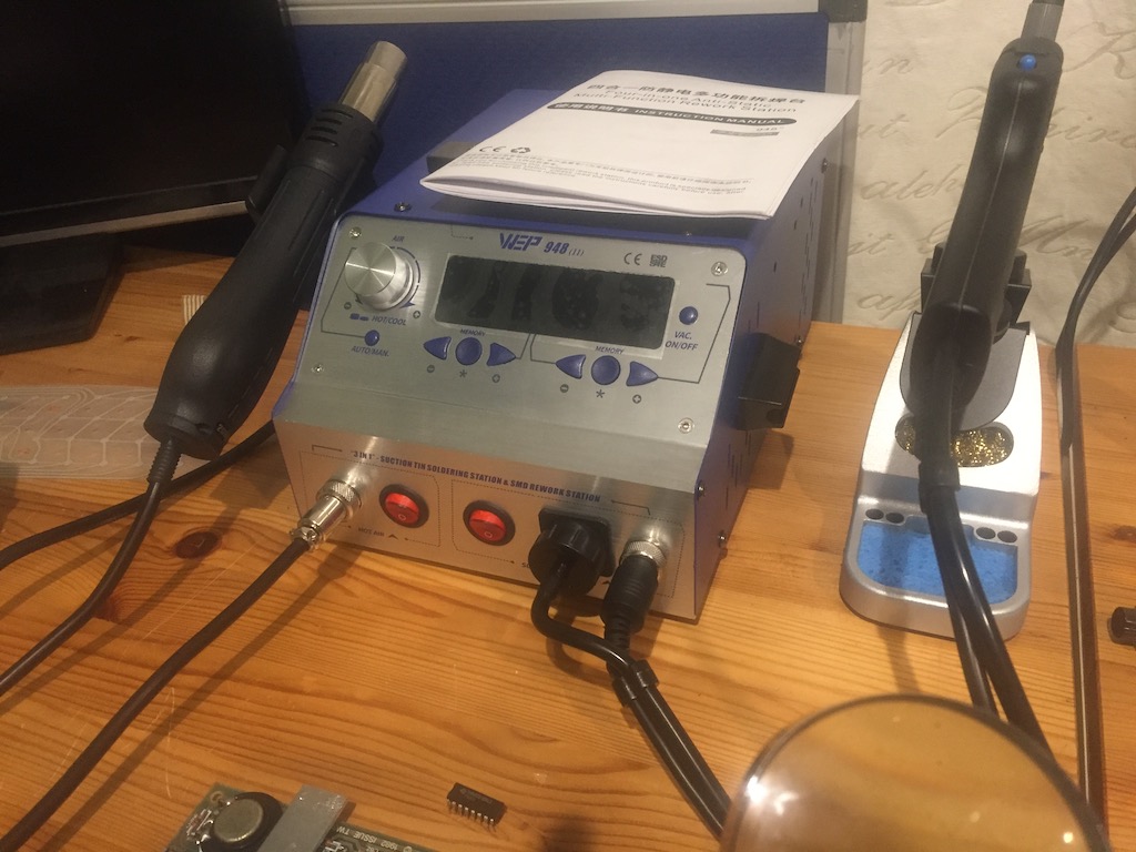
To cut a long story short, over Christmas I decided to take my retro computing hobby more seriously, so purchased a cheap desoldering station off Amazon over Christmas to assist with their repair.
This box of tricks includes a soldering iron, a hot-air gun, and a desolder gun, all thermostatically controlled from a single box.
So armed with my new toy, some trepidation and fresh enthusiasm, I decided to pick up where I left off, and sort out that top bank of RAM.
And fix the keyboard membrane, as the ribbon cables had split due to being brittle with age.
Time to hit the Internet and order some spares:
- New membrane from Dataserve Retro
- 8 x 4164 RAM chips from Retroleum
- Some 16-pin DIL chip sockets for the RAM from Amazon
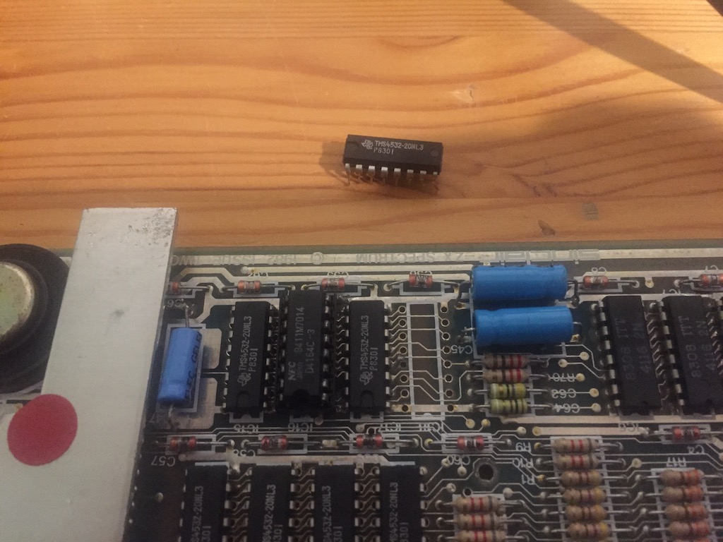
It’s worth pointing out that the 4164 RAM chips are not a like-for-like replacement for the original RAM chips. The 48K Spectrum was fitted with 32K RAM chips which were in effect 64K RAM chips with a marked fault on one bank of 32K. Depending upon your Spectrum this could be either the high or low bank, but all the chips should match – the board would be configured to address the correct half. I think Sinclair bought these chips from the manufacturer as they were cheaper than 32K RAM chips at the time. Anyway, these chips are pin-compatible with any 48K Spectrum – they are fully tested 64K chips – the Spectrum will only use one half.
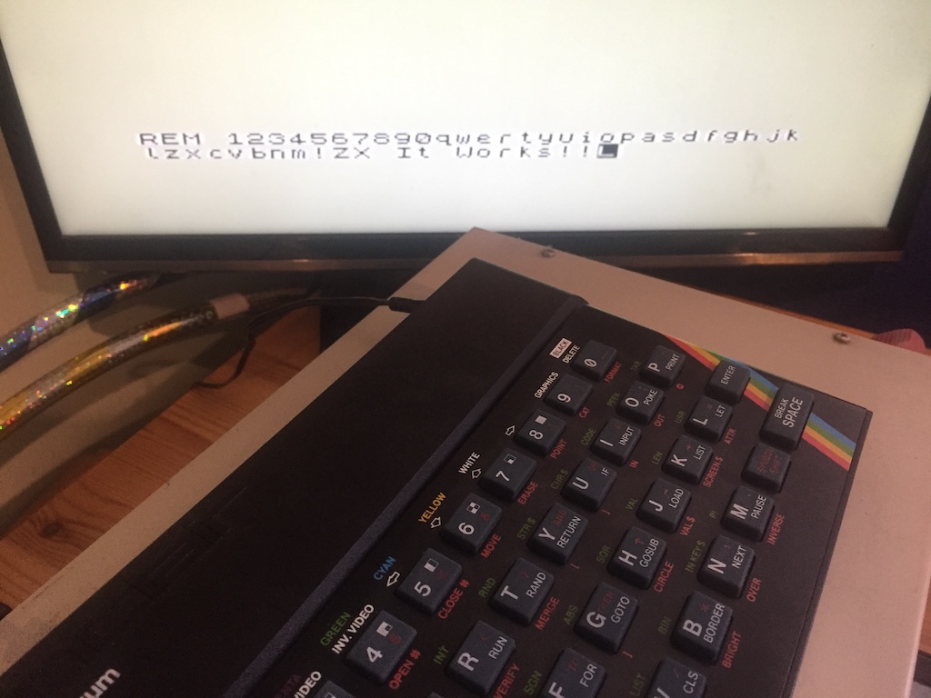
My first task was to power up the Spectrum to check that it still worked after 6 years in storage. Thankfully it booted into the copyright message just fine.
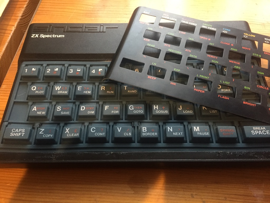
It made sense to replace and test the keyboard membrane next. A working keyboard would be required to test the memory. Whilst this is a relatively trivial task, care must be taken when removing the metal cover over the rubber mat – the adhesive is surprisingly aggressive, and it could be easily bent or scratched.
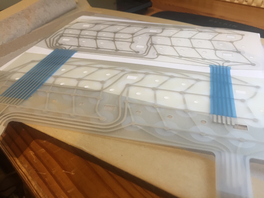
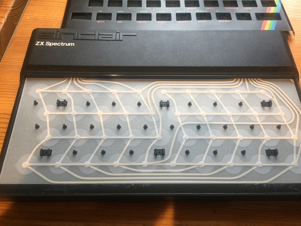
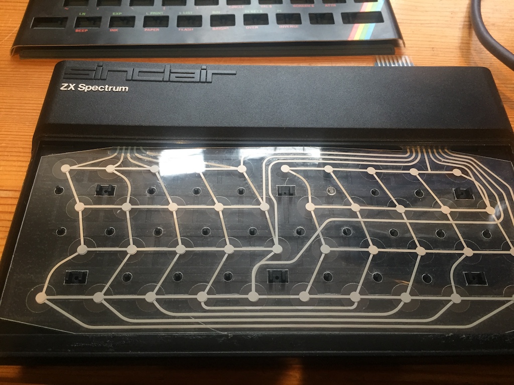
The new membrane was not supplied with the plastic tabs fitted to the end of the ribbon cables. I decided to take these off the original and glue onto the new one, in order to stiffen the cable to more easily push into the connectors on the motherboard.
The keyboard was reassembled and tested – a quick test of RAMTOP indicated this was still functioning as a 16K Spectrum – the built-in RAM test on boot will set that system variable to the last byte of workable RAM. So onto the job at hand – getting the top bank of 32K RAM working.
The desolder gun made desoldering the RAM chips a joy. I managed to desolder the 7 remaining RAM chips and the socket I’d soldered on within 30 minutes. I should have bought one of these years ago!
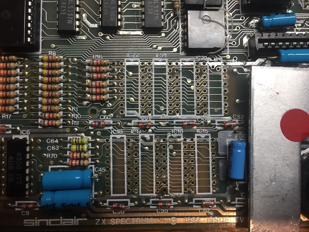
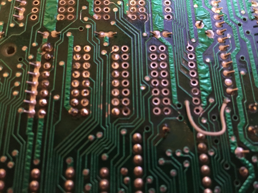
For some reason, the chips corner pins (1, 8 and 16) were soldered to the top layer. I assume this was belts-and-braces to provide a more stable +5V and ground. I managed to damage a couple of traces on the motherboard in my eagerness to pull the chips out. Lesson learned there – the traces are quite delicate (and old), so next time will use the hot-air gun to further soften any remaining solder whilst gently encouraging the chips out.
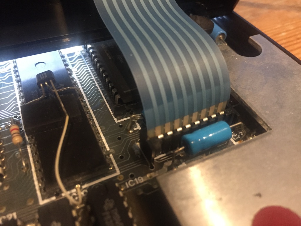
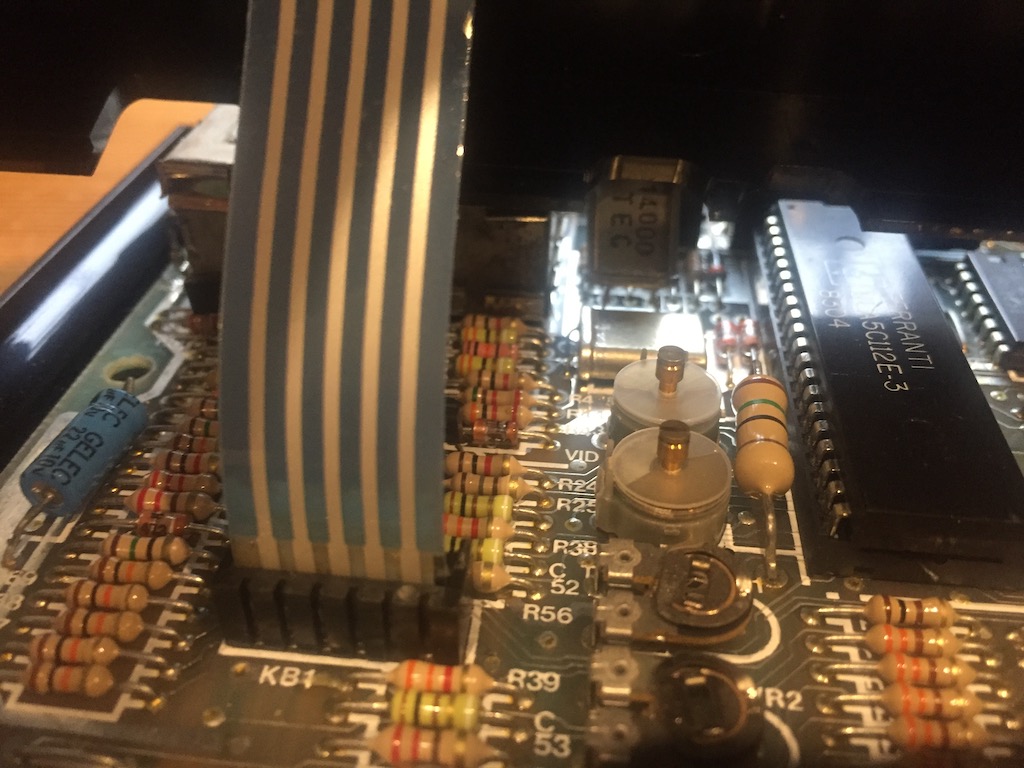
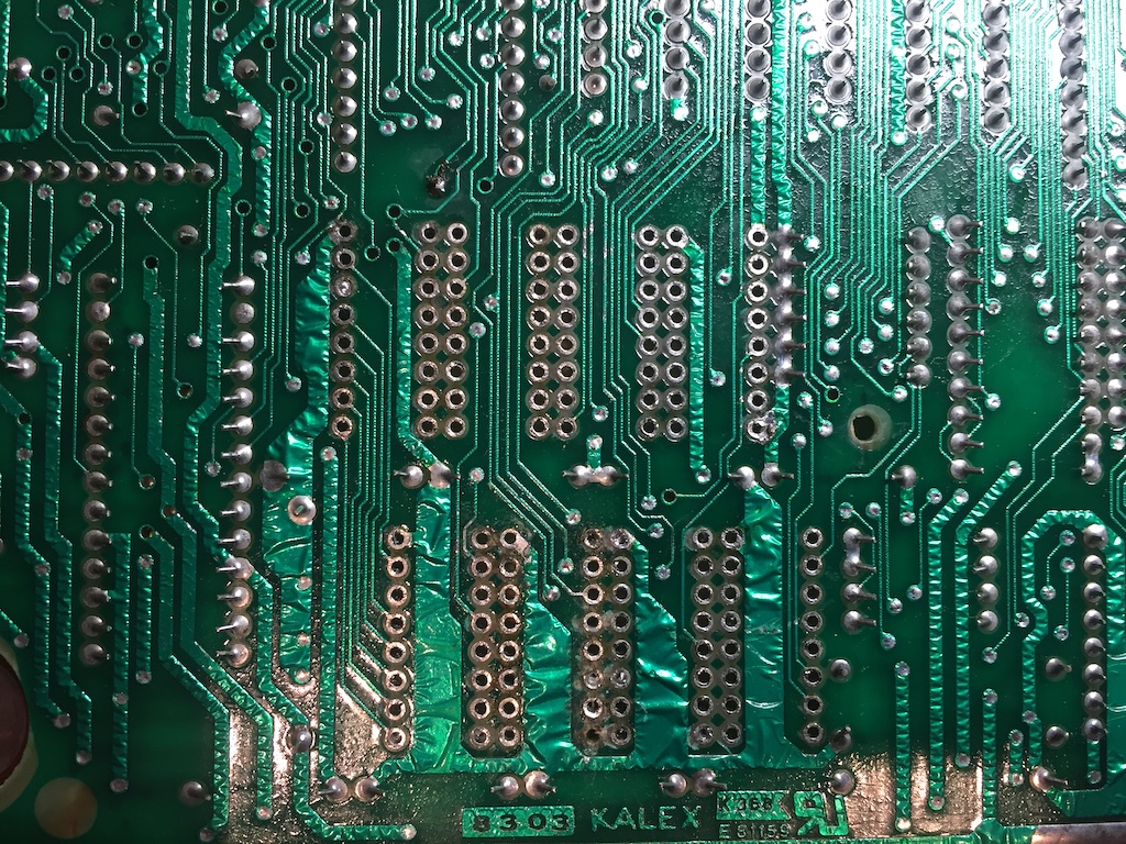
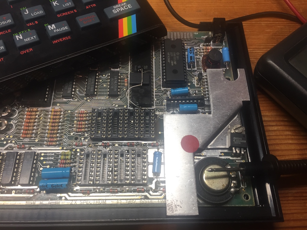
The next step was to clean up the area with some desolder braid, then solder in the sockets. I repaired the small number of broken traces under the board with thin wire bridging any breaks. Sockets seemed a sensible precaution – not sure this board would take much more rework if any of the new chips failed.
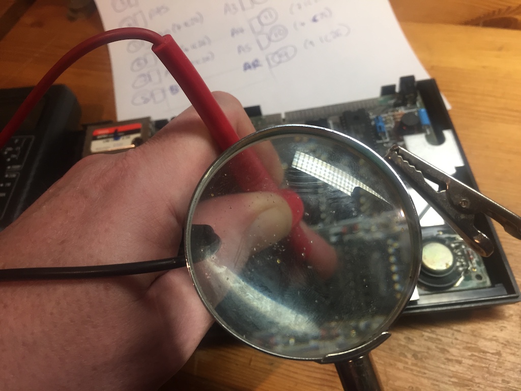
The next job was to check that all the sockets were correctly wired using the continuity beep test on my multimeter.
On each chip:
- Pins 1 and 16 are linked.
- Pins 2 and 14 are linked.
And then across the chips, all pins bar 2 and 14 should be connected between each socket.
Pins 2 and 14 are connected to the data lines on the ROM:
- IC15 to D0 (Pin 11)
- IC16 to D1 (Pin 12)
- IC17 to D2 (Pin 13)
- IC18 to D3 (Pin 15)
- IC19 to D4 (Pin 16)
- IC20 to D5 (Pin 17)
- IC21 to D6 (Pin 18)
- IC22 to D7 (Pin 19)
Finally, I quickly checked that the remaining address and select chips on the pins were connected to the memory addressing logic chips:
- Pin 3 to IC23 Pin 11
- Pin 4 to IC23 Pin 4
- Pin 5 to IC26 Pin 7
- Pin 6 to IC26 Pin 4
- Pin 7 to IC26 Pin 12
- Pin 9 to IC26 Pin 9
- Pin 10 to IC25 Pin 4
- Pin 11 to IC25 Pin 7
- Pin 12 to IC25 Pin 9
- Pin 13 to IC25 Pin 12
- Pin 15 to IC23 Pin 6
Once I’d satisfied myself that all the pins were connected, and there were no obvious short-circuits in my solder joints and trace repairs, I pushed the RAM chips into their sockets (making sure that they were all inserted Pin 1 towards the edge-connector), and powered on again.
The RAM test before the copyright message seemed to take longer than previous; this was taken to be a good sign – I’d expect that it would take longer, given it would be checking the extra 32K of RAM.
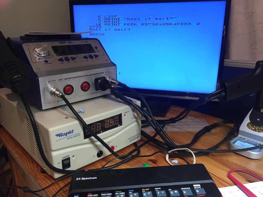
The acid test though – what was the value RAMTOP? It should be 65535 in a healthy 48K Spectrum – so off with the power, quickly install the keyboard, back on, and:
The answer returned was 65535! Result.